COMBINATION SWITCH REMOVAL
-
PRECAUTION
Note
After turning the power switch off, waiting time may be required before disconnecting the cable from the negative (-) auxiliary battery terminal. Therefore, make sure to read the disconnecting the cable from the negative (-) auxiliary battery terminal notice before proceeding with work Click here.
-
REMOVE REAR NO. 2 FLOOR BOARD
-
Remove the rear No. 2 floor board.
-
-
REMOVE REAR DECK FLOOR BOX
-
Remove the rear deck floor box.
-
-
REMOVE REAR NO. 3 FLOOR BOARD
-
Remove the rear No. 3 floor board.
-
-
REMOVE DECK FLOOR BOX RH
-
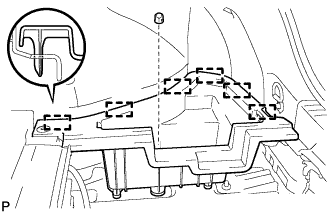
Remove the clip.
-
Disengage the 6 guides and remove the deck floor box RH.
-
-
REMOVE REAR FLOOR BOARD UPPER NO. 3 PLATE
-
Disengage the 4 claws and 2 guides, and remove the rear floor board upper No. 3 plate.
-
-
DISCONNECT CABLE FROM NEGATIVE AUXILIARY BATTERY TERMINAL
Note
When disconnecting the cable, some systems need to be initialized after the cable is reconnected Click here.
-
REMOVE LOWER CENTER INSTRUMENT PANEL FINISH PANEL
-
Open the glove compartment door.
-
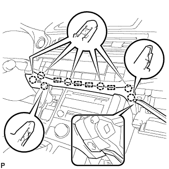
Using a moulding remover, disengage the 7 claws and 4 guides, and remove the lower center instrument panel finish panel as shown in the illustration.
-
-
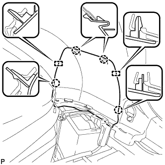
REMOVE UPPER NO. 1 CONSOLE PANEL GARNISH
-
Disengage the 4 claws, clip and 3 guides, and remove the upper No. 1 console panel garnish.
-
-
REMOVE UPPER NO. 2 CONSOLE PANEL GARNISH
-
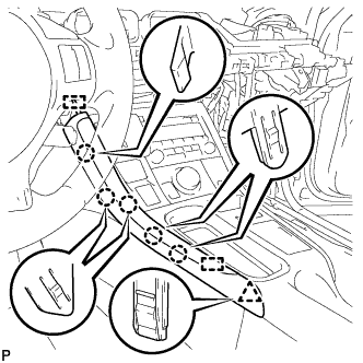
Disengage the 5 claws, clip and 2 guides, and remove the upper No. 2 console panel garnish.
-
-
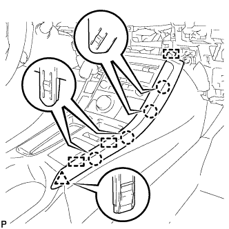
REMOVE UPPER CONSOLE PANEL SUB-ASSEMBLY
-
Open the console compartment door.
-
Using a moulding remover, disengage the 9 claws of the vehicle rear side.
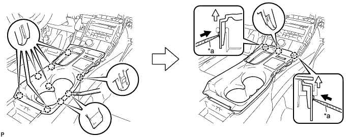
Text in Illustration *a Protective Tape - - -
Using a screwdriver with its tip wrapped with protective tape, disengage the 3 claws of the vehicle front side as shown in the illustration.
-
Disengage the clamp.
-
Disconnect each connector and remove the upper console panel sub-assembly.
-
-
REMOVE SHIFT LEVER KNOB SUB-ASSEMBLY
-
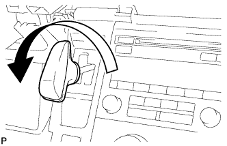
Turn the shift lever knob counterclockwise and remove the shift lever knob sub-assembly.
-
-
REMOVE COMBINATION SWITCH ASSEMBLY
-
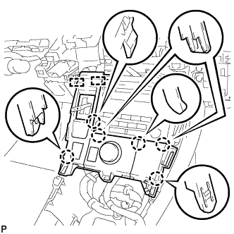
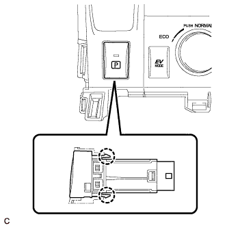
Disengage the 6 claws and 2 guides.
-
Disengage the clamp.
-
Disconnect each connector and remove the combination switch assembly.
-
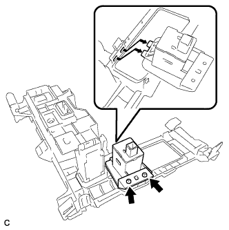
Remove the 2 screws and position indicator housing assembly from the combination switch assembly.
-
Disengage the 2 claws and remove the transmission shift main switch.
-