HV RELAY ASSEMBLY REMOVAL
-
REMOVE SERVICE PLUG GRIP
-
REMOVE INVERTER COVER ASSEMBLY LH (w/ Cover)
-
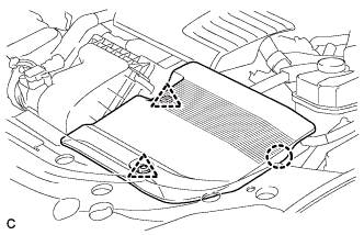
Remove the 2 clips
-
Disengage the claw and remove the inverter cover assembly LH.
-
-
REMOVE INVERTER COVER
CAUTION:
Wear insulating gloves.
-
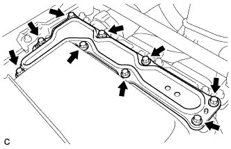
Remove the 9 bolts and inverter cover.
Note
Make sure to pull the inverter cover straight up, as a connector is connected to the bottom of the cover.
-
-
CHECK TERMINAL VOLTAGE
CAUTION:
Wear insulating gloves.
Note
Do not allow any foreign objects or water to enter the inverter with converter assembly.
-
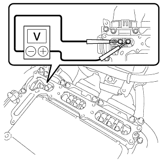
Using a voltmeter, measure the voltage between the terminals of the 2 phase connectors.
Standard voltage 0 V Tech Tips
Use measuring range of DC 750 V or more on the voltmeter.
-
-
INSTALL INVERTER COVER
CAUTION:
Wear insulating gloves.
Note
-
Make sure that the interlock is fully engaged.
-
Do not allow any foreign objects or water to enter the inverter with converter assembly.
-
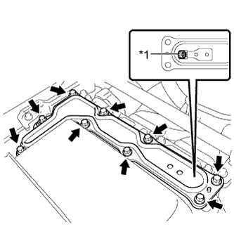
Text in Illustration *1 Interlock Install the inverter cover with the 9 bolts to the inverter with converter assembly.
- Torque:
- 11 N*m { 112 kgf*cm, 8 ft.*lbf }
-
-
INSTALL INVERTER COVER ASSEMBLY LH (w/ Cover)
-
Engage the claw and install the inverter cover assembly LH.
-
Install the 2 clips.
-
-
REMOVE TONNEAU COVER ASSEMBLY (w/ Tonneau Cover)
-
Remove the tonneau cover assembly.
-
-
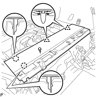
REMOVE REAR NO. 4 FLOOR BOARD (w/o Woofer)
-
Remove the rear No. 4 floor board.
-
-
REMOVE REAR NO. 4 FLOOR BOARD (w/ Woofer)
-
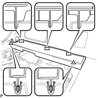
Disengage the 2 clips and 3 guides, and remove the rear No. 4 floor board.
-
-
REMOVE DECK FLOOR BOX LH (w/o Woofer)
-
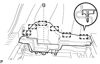
Remove the clip.
-
Disengage the 6 guides and remove the deck floor box LH.
-
-
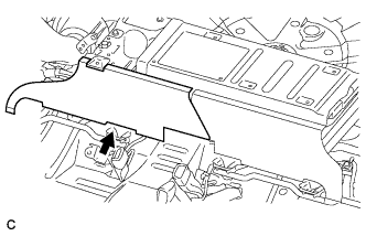
REMOVE REAR NO. 1 FLOOR BOARD SUB-ASSEMBLY
-
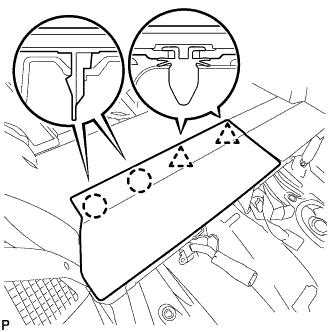
Disengage the 2 claws and 2 clips, and remove the rear No. 1 floor board sub-assembly.
-
-
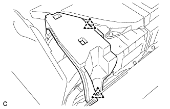
REMOVE REAR NO. 2 FLOOR BOARD SUB-ASSEMBLY
-
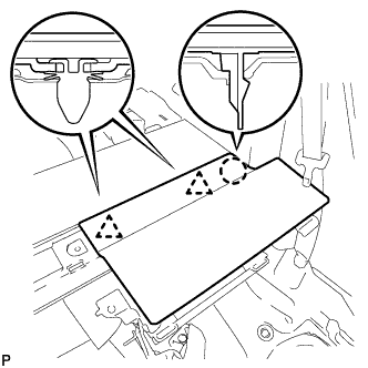
Disengage the claw and 2 clips, and remove the rear No. 2 floor board sub-assembly.
-
-
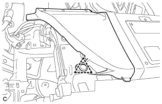
REMOVE REAR NO. 1 FLOOR BOARD
-
Remove the bolt.
-
Disengage the 2 claws and 2 clips, and remove the rear No. 1 floor board.
-
-
REMOVE REAR SEATBACK ASSEMBLY RH
-
REMOVE REAR DOOR SCUFF PLATE RH
Tech Tips
Use the same procedure as for the LH side Click here.
-
REMOVE REAR SEAT SIDE GARNISH RH
Tech Tips
Use the same procedure as for the LH side Click here.
-
REMOVE HV BATTERY SHIELD SHEET
Remove the hybrid vehicle battery shield sheet.
-
REMOVE REAR FLOOR BOARD SPACER
-
Remove the 2 clips and rear floor board spacer.
-
-
REMOVE NO. 1 HYBRID BATTERY EXHAUST DUCT
-
Remove the clip and No. 1 hybrid battery exhaust duct.
-
-
REMOVE UPPER HYBRID BATTERY COVER SUB-ASSEMBLY
CAUTION:
Be sure to wear insulated gloves and protective goggles.
-
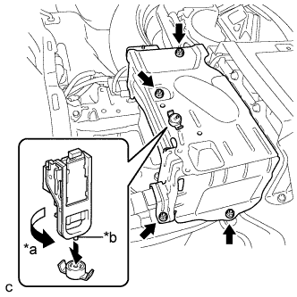
Text in Illustration *a Turn *b Projection Using the service plug grip, remove the battery cover lock striker.
Tech Tips
Insert the projection part of the service plug grip, and turn the button of the battery cover lock striker counterclockwise, and release the lock.
-
Remove the 4 nuts and upper hybrid battery cover sub-assembly.
-
-
DISCONNECT FRAME WIRE
CAUTION:
-
Wear insulated gloves.
-
Insulate the removed terminals with insulating tape.
-
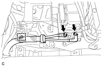
Remove the 2 nuts, then disconnect the frame wire from the hybrid battery junction block.
-
Disconnect the clamp and frame wire.
-
-
REMOVE HYBRID BATTERY JUNCTION BLOCK ASSEMBLY
CAUTION:
Be sure to wear insulated gloves.
Note
Insulate the disconnected terminals with insulating tape.
-
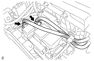
Disconnect the 2 connectors from the hybrid battery junction block assembly.
-
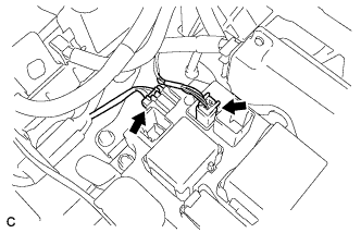
Disconnect the 2 connectors from the hybrid battery junction block assembly.
-
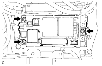
Remove the 3 nuts and hybrid battery junction block assembly.
-