FRAME WIRE REMOVAL
-
PRECAUTION
Note
After turning the power switch off, waiting time may be required before disconnecting the cable from the negative (-) auxiliary battery terminal. Therefore, make sure to read the disconnecting the cable from the negative (-) auxiliary battery terminal notice before proceeding with work Click here.
-
REMOVE SERVICE PLUG GRIP
-
REMOVE TONNEAU COVER ASSEMBLY (w/ Tonneau Cover)
-
Remove the tonneau cover assembly.
-
-
REMOVE REAR NO. 4 FLOOR BOARD (w/o Woofer)
-
Remove the rear No. 4 floor board.
-
-
REMOVE REAR NO. 4 FLOOR BOARD (w/ Woofer)
-
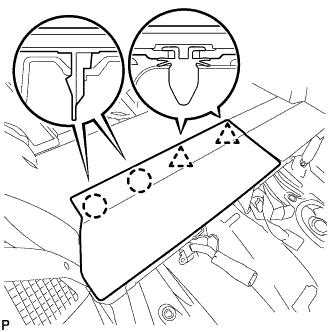
Disengage the 2 clips and 3 guides, and remove the rear No. 4 floor board.
-
-
REMOVE DECK FLOOR BOX LH (w/o Woofer)
-
Remove the clip.
-
Disengage the 6 guides and remove the deck floor box LH.
-
-
REMOVE INVERTER WITH CONVERTER ASSEMBLY
-
REMOVE FRONT EXHAUST PIPE ASSEMBLY
-
REMOVE FRONT NO. 1 FLOOR HEAT INSULATOR
-
Remove the 3 nuts and front No. 1 floor heat insulator.
-
-
REMOVE FRONT FLOOR COVER RH (w/ Cover)
-
Remove the bolt
-
Remove the 4 clips and the front floor cover RH.
-
-
REMOVE FRONT CENTER FLOOR COVER RH (w/ Cover)
-

Remove the 3 clips and the front floor cover center RH.
-
-
REMOVE FRONT SUSPENSION MEMBER BRACE REAR RH
-
Using a transmission jack, hold the front suspension cross member.
Note
Be sure to position the transmission jack to properly support the front suspension cross member.
-
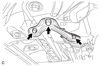
Remove the 3 bolts and front suspension member brace rear RH.
-
-
REMOVE REAR SEATBACK ASSEMBLY RH
-
REMOVE REAR DOOR SCUFF PLATE RH
Tech Tips
Use the same procedure described for the LH side Click here.
-
REMOVE REAR SEAT SIDE GARNISH RH
Tech Tips
Use the same procedure described for the LH side Click here.
-
REMOVE REAR NO. 1 FLOOR BOARD SUB-ASSEMBLY
-
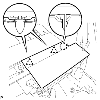
Disengage the 2 claws and 2 clips, and remove the rear No. 1 floor board sub-assembly.
-
-
REMOVE REAR NO. 2 FLOOR BOARD SUB-ASSEMBLY
-
Disengage the claw and 2 clips, and remove the rear No. 2 floor board sub-assembly.
-
-
REMOVE REAR NO. 1 FLOOR BOARD
-
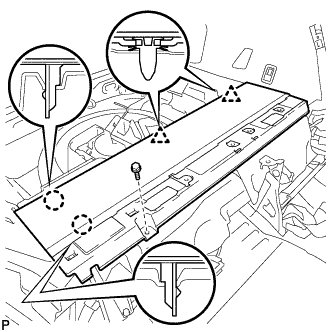
Remove the bolt.
-
Disengage the 2 claws and 2 clips, and remove the rear No. 1 floor board.
-
-
REMOVE HV BATTERY SHIELD SHEET
Remove the hybrid vehicle battery shield sheet.
-
REMOVE REAR FLOOR BOARD SPACER
-
Remove the 2 clips and rear floor board spacer.
-
-
REMOVE NO. 1 HYBRID BATTERY INTAKE DUCT
-
Remove the 2 clips and No. 1 hybrid battery intake duct.
-
-
REMOVE NO. 1 HYBRID BATTERY EXHAUST DUCT
-
Remove the clip and No. 1 hybrid battery exhaust duct.
-
-
REMOVE UPPER HYBRID BATTERY COVER SUB-ASSEMBLY
CAUTION:
Be sure to wear insulated gloves and protective goggles.
-
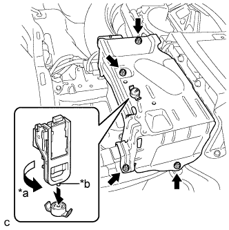
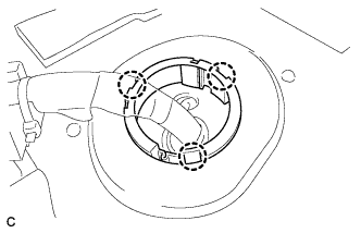
Text in Illustration *a Turn *b Projection Using the service plug grip, remove the battery cover lock striker.
Tech Tips
Insert the projection part of the service plug grip, and turn the button of the battery cover lock striker counterclockwise, and release the lock.
-
Remove the 4 nuts and upper hybrid battery cover sub-assembly.
-
-
DISCONNECT CABLE FROM AUXILIARY BATTERY TERMINAL
-
Remove the connector cover.
-
Disconnect the clamp, and remove the nut.
-
Disconnect the clamp.
-
Disconnect the 2 wire harness clamps.
-
Disconnect the 2 wire harness clamps.
-
-
DISCONNECT HYBRID BATTERY JUNCTION BLOCK ASSEMBLY
CAUTION:
Wear insulating gloves.
Note
Insulate the disconnected terminals with insulating tape.
-
Remove the 2 nuts, then disconnect the frame wire from the hybrid battery junction block assembly.
-
Disconnect the clamp and frame wire.
-
-
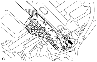
REMOVE INVERTER RESERVE TANK ASSEMBLY
-

Remove the 2 bolts and separate the inverter reserve tank assembly.
-
-
REMOVE FRAME WIRE
CAUTION:
Wear insulating gloves.
Note
Insulate the disconnected terminals with insulating tape.
-
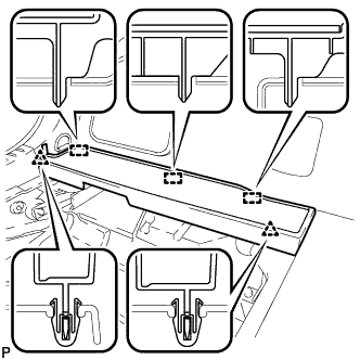
Remove the wire harness protector and disconnect the clamp from the floor panel.
-
Disconnect the 2 wire harness clamps from the floor panel.
-
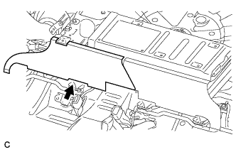
Disconnect the 3 claws and push the frame wire out from the floor panel.
-
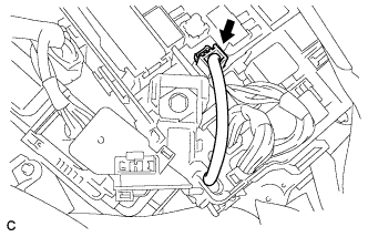
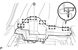
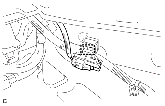
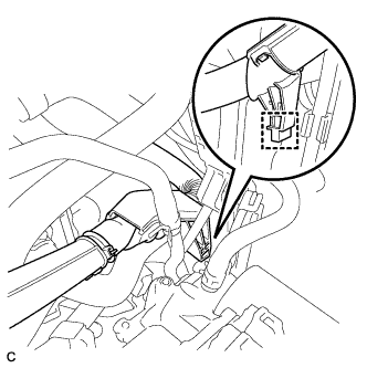
Disconnect the connector from the engine room junction block assembly.
-
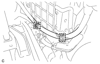
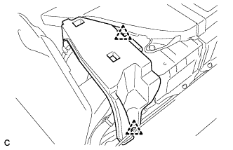
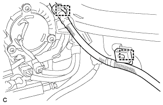
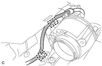
Disconnect the 2 clamps shown in the illustration.
-
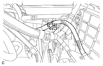
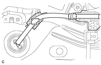
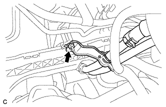
Disconnect the clamp shown in the illustration.
-
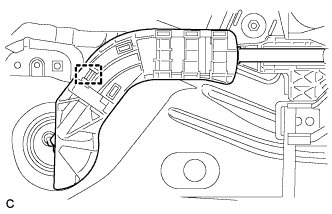
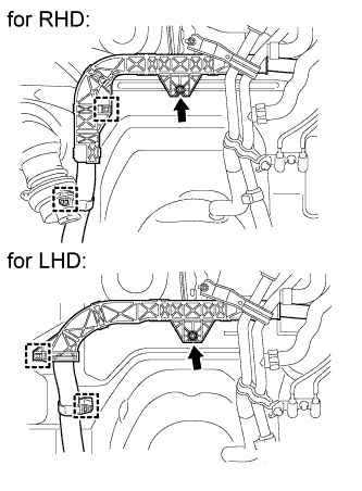
Disconnect the clamp shown in the illustration.
-
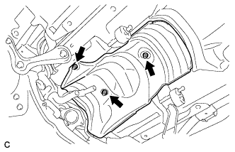
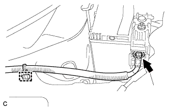
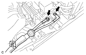
Remove the nut and separate the heater water pipe sub-assembly.
-
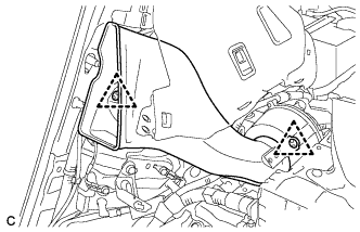
Remove the nut and 2 clamps shown in the illustration.
-
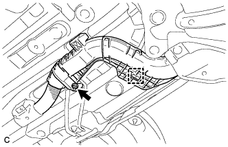
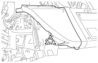
Remove the nut and clamp shown in the illustration.
-
Remove the nut shown in the illustration.
-
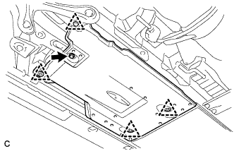
Disconnect the 4 clamps and remove the frame wire.
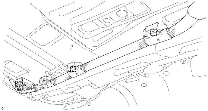
Note
The clamps are non-reusable parts.
-