For the assembly procedure of the inverter with converter assembly, refer to the assembly procedure of the MG control computer with bracket sub-assembly. (Click here)
- Click here
INSTALL INVERTER WIRE SUB-ASSEMBLY
Note: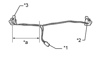
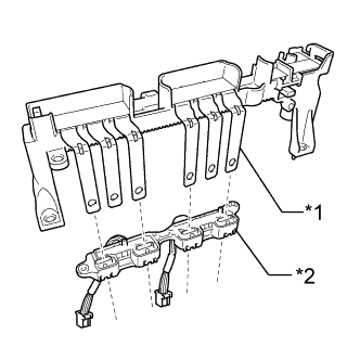
Compare the length of the wire harness from each interlock connector to the branching point. The interlock connector on the shorter side of the wire harness is referred to as the interlock connector (B).
Table 1. Text in Illustration *1 Branching Point (Connector A) *2 Inter Lock Connector A *3 Inter Lock Connector B *a Shorter
-
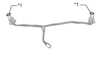
Apply protective tape to the inverter wire sub-assembly as shown in the illustration.
Note:Use non-residue type tape.
Table 2. Text in Illustration *1 Protective Tape -
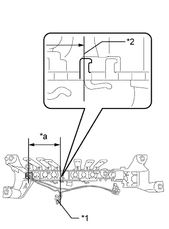
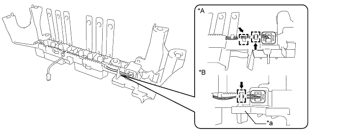
Set the inverter terminal sub-assembly as shown in the illustration and confirm the installation position of the inverter wire sub-assembly.
Table 3. Text in Illustration *1 Connector A *2 Clamp *a Shorter -
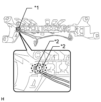
Engage the 2 claws to connect the interlock connector (B) to the inverter terminal sub-assembly as shown in the illustration.
Tip:Push in the protruding part of the interlock connector (B) and make sure that it is securely installed.
Table 4. Text in Illustration *1 Inter Lock Connector B *2 Claw -
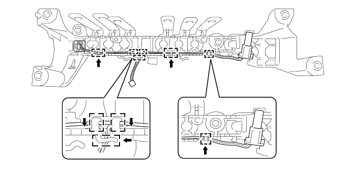
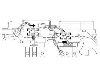
Engage the wire harness of the inverter wire sub-assembly to the 6 clamps as shown in the illustration.
Note: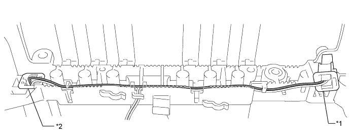
Make sure that the wire which connects the interlock connectors is on the top of the other wires and not twisted.
Table 5. Text in Illustration *1 Inter Lock Connector A *2 Inter Lock Connector B -
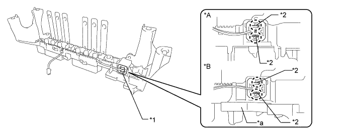
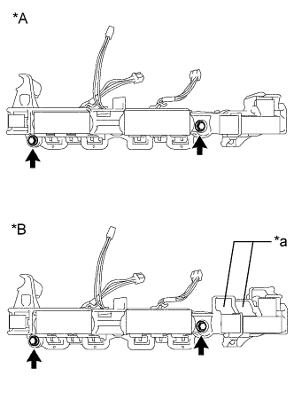
Engage the 2 claws to connect the interlock connector (A) to the inverter terminal sub-assembly as shown in the illustration.
Table 6. Text in Illustration *A Type 1 *B Type 2 *1 Inter Lock Connector A *2 Claw *a Terminal Tray - - Tip:Push in the protruding part of the interlock connector (A) and make sure that it is securely installed.
-
Engage the wire harness of the inverter wire sub-assembly to each clamp to install it as shown in the illustration.
Note:Do not pull the wire harness excessively.
Tip:The number of clamps used to engage the wire harnesses of the inverter wire sub-assembly varies depending on the part number of the inverter with converter assembly. Confirm the part number before performing work.
Table 7. Text in Illustration *A Type 1 *B Type 2 *a Terminal Tray - - -
Check the installation condition of the inverter wire sub-assembly.
Note:Make sure that the wire harness of inverter wire sub-assembly is not twisted.
-
- Click here
INSTALL INVERTER CURRENT SENSOR SUB-ASSEMBLY
-
Insert the bus-bars of the inverter terminal sub-assembly into the inverter current sensor sub-assembly as shown in the illustration.
Table 8. Text in Illustration *1 Bus-bar *2 inverter current sensor sub-assembly -
Install the inverter current sensor sub-assembly with the 2 bolts.
5.0 N*m 51 kgf*cm 44 in.*lbf Table 9. Text in Illustration *A Type 1 *B Type 2 *a Terminal Tray -
Engage the wire harness of inverter current sensor sub-assembly to the 2 clamps as shown in the illustration.
Tip:
-
Although the number of clamps which the wire harnesses of the inverter current sensor sub-assembly are disengaged from during removal varies depending on the part number of the inverter with converter assembly, only 2 clamps will be used to engage the wire harness during installation.
-
The position of the connectors on the MG control computer with bracket sub-assembly side depend on the part number of the inverter with converter assembly.
-
-
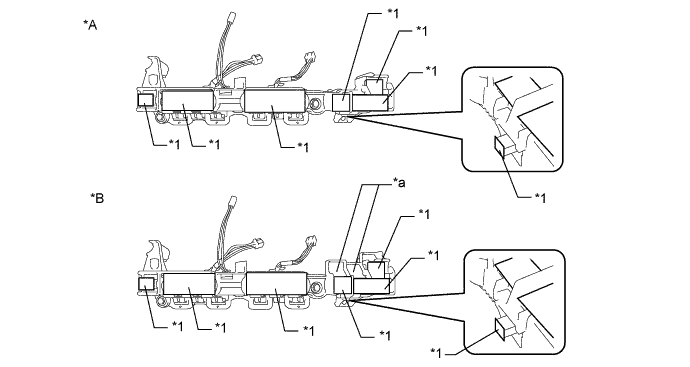
Remove the protective tape.
Table 10. Text in Illustration *A Type 1 *B Type 2 *1 Protective Tape - - *a Terminal Tray - -
-