HYBRID BATTERY SYSTEM, Diagnostic DTC:P0A9C-123, P0AC6-123, P0ACB-123, P3065-123
| DTC Code | DTC Name |
|---|---|
| P0A9C-123 | Hybrid Battery Temperature Sensor "A" Range / Performance |
| P0AC6-123 | Hybrid Battery Temperature Sensor "B" Range / Performance |
| P0ACB-123 | Hybrid Battery Temperature Sensor "C" Range / Performance |
| P3065-123 | Hybrid Battery Temperature Sensor Range/Performance Stuck "A" |
DESCRIPTION
-
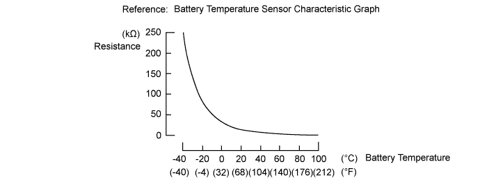
The battery temperature sensors are provided at 3 locations of the HV battery. The resistance of the thermistor, which is built into each battery temperature sensor, varies in accordance with changes in the HV battery temperature. The lower the battery temperature, the higher the thermistor resistance. Conversely, the higher the temperature, the lower the resistance. The battery smart unit uses the battery temperature sensors to detect the HV battery temperature, and sends the detected value to the power management control ECU. Based on the results of this detection, the power management control ECU controls the blower fan. (The blower fan starts when HV battery temperature rises above a predetermined level.)
Temperature Sensor Identification Cross Reference Table DTC Title Sensor Battery Temperature Sensor Intelligent Tester Display A 0 1 B 1 2 C 2 3 Tech Tips
For example, sensor A in the DTC title is battery temperature sensor (No. 0). This sensor is displayed as Temp of Batt TB1 in the Data List.
| DTC No. | DTC Detection Condition | Trouble Area |
|---|---|---|
| P0A9C-123 P0AC6-123 P0ACB-123 P3065-123 |
When the battery temperature sensor performance is abnormal (1 trip detection/2 trip detection) |
|
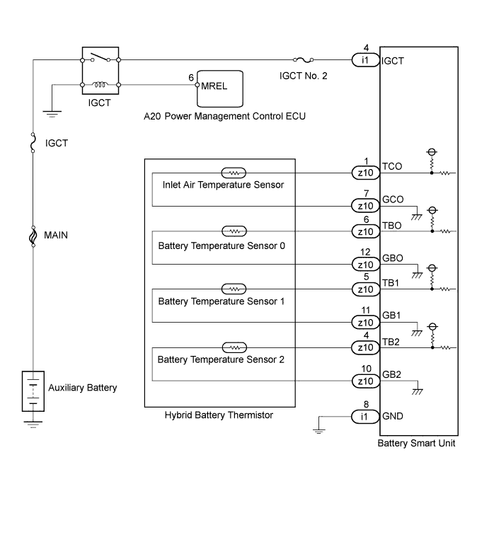
WIRING DIAGRAM
INSPECTION PROCEDURE
CAUTION:
-
Before inspecting the high-voltage system, take safety precautions to prevent electrical shocks, such as wearing insulated gloves and removing the service plug grip. After removing the service plug grip, put it in your pocket to prevent other technicians from accidentally reconnecting it while you are working on the high-voltage system.
-
After removing the service plug grip, wait for at least 10 minutes before touching any of the high-voltage connectors or terminals. After waiting for 10 minutes, check the voltage at the terminals in the inspection point in the inverter with converter assembly. The voltage should be 0 V before beginning work Click here.
Tech Tips
Waiting for at least 10 minutes is required to discharge the high-voltage capacitor inside the inverter with converter assembly.
Note
After turning the power switch off, waiting time may be required before disconnecting the cable from the negative (-) auxiliary battery terminal. Therefore, make sure to read the disconnecting the cable from the negative (-) auxiliary battery terminal notices before proceeding with work Click here.
PROCEDURE
-
CHECK DTC OUTPUT (HV)
-
Connect the intelligent tester to the DLC3.
-
Turn the power switch on (IG).
-
Enter the following menus: Powertrain / Hybrid Control / DTC.
-
Check if DTCs are output.
Result Result Proceed to P0AFC-123 is not output. A P0AFC-123 is also output. B -
Turn the power switch off.
B 
GO TO DTC CHART Click here
A 
-
-
CHECK INSTALLATION OF BATTERY TEMPERATURE SENSOR
CAUTION:
Be sure to wear insulated gloves and protective goggles.
-
Check that the service plug grip is not installed.
Note
After removing the service plug grip, do not turn the power switch on (READY), unless instructed by the repair manual because this may cause a malfunction.
-
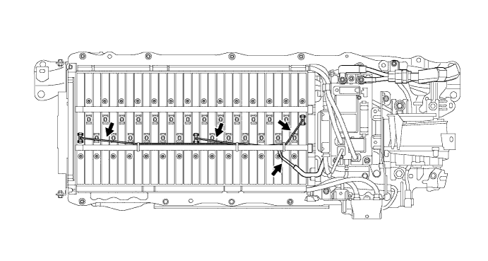
Visually check the installation condition of the relevant battery temperature sensor.
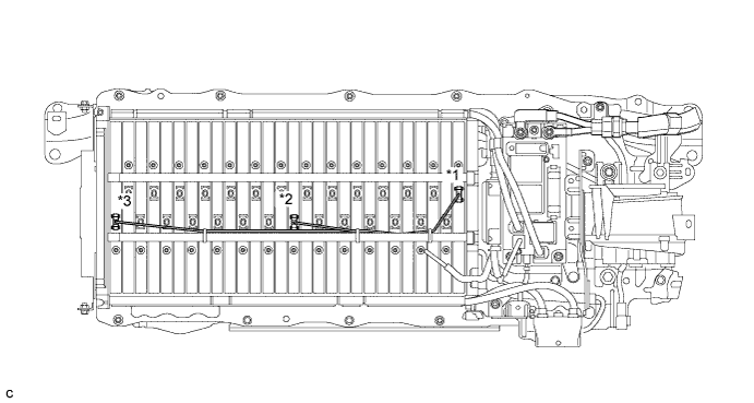
Text in Illustration *1 Battery Temperature Sensor 0 *2 Battery Temperature Sensor 1 *3 Battery Temperature Sensor 2 - - Standard Condition Each battery temperature sensor is installed in the correct location with the correct orientation and its claws are engaged securely. Result Result Proceed to Each battery temperature sensor is installed in the correct location with the correct orientation and its claws are engaged securely. A Claws are damaged. B Any of battery temperature sensors are not installed correctly, but claws are not damaged. C Note
Do not use a stick or similar object to push on the sensors when inspecting them. Doing so may result in damage to the sensors.
B
REPLACE HYBRID BATTERY THERMISTOR Click here
C
INSTALL PARTS CORRECTLY
A
-
-
CHECK HYBRID BATTERY THERMISTOR (BATTERY TEMPERATURE SENSOR)
CAUTION:
Be sure to wear insulated gloves.
-
Check that the service plug grip is not installed.
Note
After removing the service plug grip, do not turn the power switch on (READY), unless instructed by the repair manual because this may cause a malfunction.
-
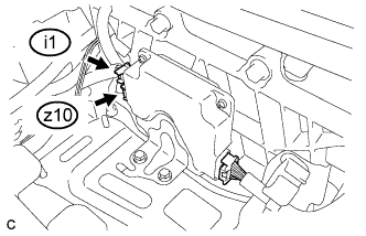
Disconnect connectors z10 and i1 from the battery smart unit.
-
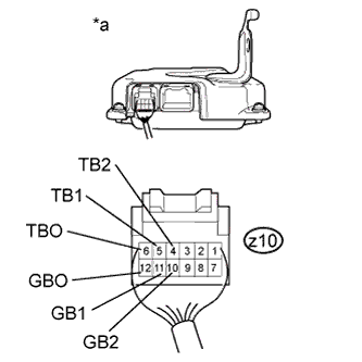
Text in Illustration *a Rear view of wire harness connector
(to Battery Smart Unit)
Measure the resistance of the circuit for the malfunctioning sensor (battery temperature sensor 0 to 2).
Tester Connection Tester Connection Battery Temperature Sensor No. z10-6 (TBO) - z10-12 (GBO) 0 z10-5 (TB1) - z10-11 (GB1) 1 z10-4 (TB2) - z10-10 (GB2) 2 Standard Resistance Thermistor Temperature Switch Condition Specified Condition 0°C (32°F) Power switch off 26.7 to 27.8 kΩ 25°C (77°F) Power switch off 9.9 to 10.1 kΩ 40°C (104°F) Power switch off 5.73 to 5.92 kΩ -
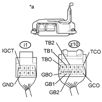
Text in Illustration *a Rear view of wire harness connector
(to Battery Smart Unit)
Measure the resistance according to the value(s) in the table below.
Standard Resistance Tester Connection Switch Condition Standard Resistance z10-6 (TBO) - i1-4 (IGCT) Power switch off 10 kΩ or higher z10-6 (TBO) - i1-8 (GND) Power switch off 10 kΩ or higher z10-12 (GBO) - i1-4 (IGCT) Power switch off 10 kΩ or higher z10-12 (GBO) - i1-8 (GND) Power switch off 10 kΩ or higher z10-5 (TB1) - i1-4 (IGCT) Power switch off 10 kΩ or higher z10-5 (TB1) - i1-8 (GND) Power switch off 10 kΩ or higher z10-11 (GB1) - i1-4 (IGCT) Power switch off 10 kΩ or higher z10-11 (GB1) - i1-8 (GND) Power switch off 10 kΩ or higher z10-4 (TB2) - i1-4 (IGCT) Power switch off 10 kΩ or higher z10-4 (TB2) - i1-8 (GND) Power switch off 10 kΩ or higher z10-10 (GB2) - i1-4 (IGCT) Power switch off 10 kΩ or higher z10-10 (GB2) - i1-8 (GND) Power switch off 10 kΩ or higher z10-1 (TCO) - i1-4 (IGCT) Power switch off 10 kΩ or higher z10-1 (TCO) - i1-8 (GND) Power switch off 10 kΩ or higher z10-7 (GCO) - i1-4 (IGCT) Power switch off 10 kΩ or higher z10-7 (GCO) - i1-8 (GND) Power switch off 10 kΩ or higher -
Connect the battery smart unit connectors.
NG 
CHECK HARNESS AND CONNECTOR (BATTERY TEMPERATURE SENSOR) Click here
OK 
REPLACE BATTERY SMART UNIT Click here
-
-
CHECK HARNESS AND CONNECTOR (BATTERY TEMPERATURE SENSOR)
CAUTION:
Be sure to wear insulated gloves and protective goggles.
-
Check that the service plug grip is not installed.
Note
After removing the service plug grip, do not turn the power switch on (READY), unless instructed by the repair manual because this may cause a malfunction.
-
Check the wire harness and connectors of the battery temperature sensor for abnormalities by sight and touch.
Specified Condition There are no open or short circuits in the wire harness and connectors. There are no short circuits to other wire harnesses.
NG
REPAIR HARNESS OR CONNECTOR
OK
REPLACE HYBRID BATTERY THERMISTOR Click here
-