EXHAUST MANIFOLD INSTALLATION

-
INSTALL NO. 2 EXHAUST MANIFOLD HEAT INSULATOR
-
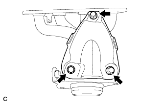
Install the No. 2 exhaust manifold heat insulator with the 3 bolts.
- Torque:
- 12 N*m { 122 kgf*cm, 9 ft.*lbf }
-
-
INSTALL EXHAUST MANIFOLD
-
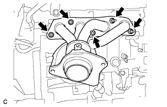
Install a new gasket and the exhaust manifold with the 5 nuts.
- Torque:
- 21 N*m { 214 kgf*cm, 15 ft.*lbf }
-
-
INSTALL MANIFOLD STAY
-
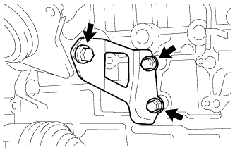
Install the manifold stay with the 3 bolts.
- Torque:
- 43 N*m { 438 kgf*cm, 32 ft.*lbf }
-
-
INSTALL AIR FUEL RATIO SENSOR
-
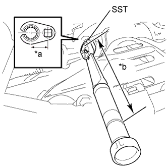
Text in Illustration *a Fulcrum Length
30 mm
*b Fulcrum Length
300 mm
Using SST, install the air fuel ratio sensor.
- SST
- 09224-00010
- Torque:
- without SST
- 44 N*m { 449 kgf*cm, 32 ft.*lbf }
- with SST
- 40 N*m { 408 kgf*cm, 30 ft.*lbf }
Note
-
The "with SST" torque value is effective when using SST with a fulcrum length of 30 mm (1.18 in.) and a torque wrench with a fulcrum length of 300 mm (11.8 in.) Click here.
-
The "with SST" torque value is effective when SST is parallel to the torque wrench.
-
Connect the air fuel ratio sensor connector and clamp.
-
-
INSTALL NO. 1 EXHAUST MANIFOLD HEAT INSULATOR
-
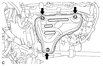
Install the No. 1 exhaust manifold heat insulator with the 3 bolts.
- Torque:
- 12 N*m { 122 kgf*cm, 9 ft.*lbf }
-
-
INSTALL FRONT NO. 1 FLOOR HEAT INSULATOR
-
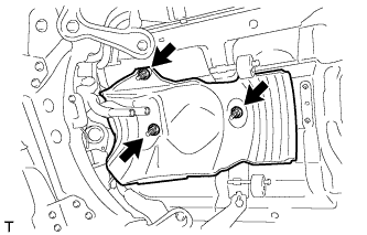
Install the No. 1 floor heat insulator with the 3 nuts.
- Torque:
- 5.5 N*m { 56 kgf*cm, 49 in.*lbf }
-
-
INSTALL FRONT EXHAUST PIPE ASSEMBLY
-
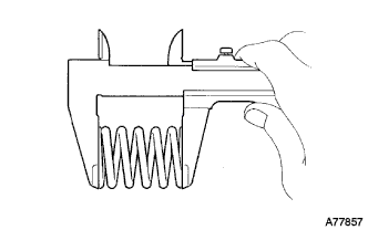
Using a vernier caliper, measure the free length of the compression springs.
Minimum (front) 41.5 mm (1.64 in.) Minimum (rear) 38.5 mm (1.52 in.) Tech Tips
If the free length is less than minimum, replace the compression spring.
-
Fully insert 2 new gaskets to the exhaust manifold and front exhaust pipe assembly.
-
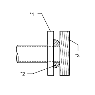
Text in Illustration *1 Exhaust Manifold and Front Exhaust Pipe Assembly *2 Gasket *3 Wooden Block Using a plastic hammer and wooden block, tap in each new gasket until its surface is flush with the exhaust manifold and front exhaust pipe assembly.
Note
-
Be careful with the installation direction of the gaskets.
-
Do not reuse the gaskets.
-
Do not damage the gaskets.
-
Do not push in the gasket by using the exhaust pipe when connecting it.
-
-
Connect the front exhaust pipe assembly to the 2 exhaust pipe supports.
-
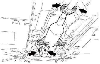
Install the front exhaust pipe assembly with the 4 bolts and 4 compression springs.
- Torque:
- 43 N*m { 438 kgf*cm, 32 ft.*lbf }
-
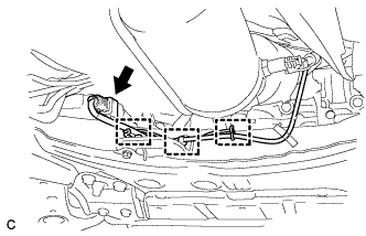
Connect the 3 clamps and oxygen sensor connector.
-
-
INSTALL FRONT CENTER FLOOR BRACE
-
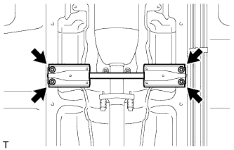
Install the front center floor brace with the 4 bolts.
- Torque:
- 51 N*m { 520 kgf*cm, 38 ft.*lbf }
-
-
INSTALL FRONT NO. 3 ENGINE UNDER COVER
-
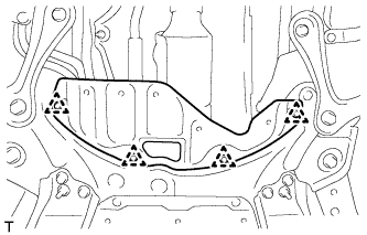
Install the front No. 3 engine under cover with the 4 clips.
-
-
INSTALL NO. 1 ENGINE UNDER COVER
-
INSTALL NO. 2 CYLINDER HEAD COVER
-
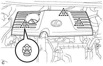
Engage the 3 clips to install the cover.
Note
-
Be sure to engage the clips securely.
-
Do not apply excessive force or hit the cover to engage the clips. This may cause the cover to break.
-
-
-
INSTALL OUTER COWL TOP PANEL SUB-ASSEMBLY
-
Install the outer cowl top panel sub-assembly with the 9 bolts.
- Torque:
- 12 N*m { 122 kgf*cm, 9 ft.*lbf }
-
w/ Wiper Deicer:
Engage the 3 clamps to install the wire harness.
-
Engage the clamp to install the wire harness.
-
-
INSTALL COWL BODY MOUNTING REINFORCEMENT LH
-
Install the cowl body mounting reinforcement LH with the 2 bolts.
- Torque:
- 12 N*m { 122 kgf*cm, 9 ft.*lbf }
-
-
INSTALL NO. 2 HEATER AIR DUCT SPLASH SHIELD SEAL
-
Engage the claw and guide to install the No. 2 heater air duct splash shield seal.
-
-
REMOVE NO. 1 HEATER AIR DUCT SPLASH SHIELD SEAL
-
Engage the 2 claws to install the No. 1 heater air duct splash shield seal.
-
-
INSTALL WINDSHIELD WIPER MOTOR AND LINK ASSEMBLY
-
INSPECT FOR EXHAUST GAS LEAK