HYBRID CONTROL SYSTEM, Diagnostic DTC:P0851-579, P0852-580
| DTC Code | DTC Name |
|---|---|
| P0851-579 | Park / Neutral Switch Input Circuit Low |
| P0852-580 | Park / Neutral Switch Input Circuit High |
DESCRIPTION
-
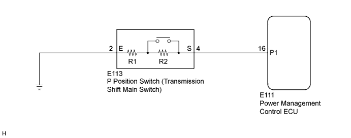
Instead of having a parking position as one of the positions of the conventional shift lever, a P position switch (transmission shift main switch) is provided independently above the shift lever. The switch is a momentary type, in which the button does not lock mechanically.
-
The P position switch (transmission shift main switch) contains resistors R1 and R2. When the P position switch (transmission shift main switch) is not pressed, the switch provides a combined resistance of R1 and R2; and when the P position switch (transmission shift main switch) is pressed, the switch provides only the resistance of R1. The voltage at the P1 terminal of the power management control ECU (HV CPU) varies with the changes in the resistance of the switch. The power management control ECU (HV CPU) determines the P position switch (transmission shift main switch) operation according to this resistance signal.
| DTC No. | INF Code | DTC Detection Condition | Trouble Area |
|---|---|---|---|
| P0851 | 579 | GND short in P position switch circuit |
|
| P0852 | 580 | Open or +B short in P position switch circuit |
INSPECTION PROCEDURE
PROCEDURE
-
INSPECT TRANSMISSION SHIFT MAIN SWITCH
-
Disconnect connector E113 from the P position switch (transmission shift main switch).
-
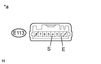
Text in Illustration *a Component without harness connected
(P Position Switch (Transmission Shift Main Switch))
Measure the resistance according to the value(s) in the table below.
Standard Resistance Tester Connection Switch Condition Specified Condition E113-4 (S) - E113-2 (E) Switch pressed 680 Ω E113-4 (S) - E113-2 (E) Switch released 4580 Ω Tech Tips
Terminals No. 1 and No. 8 on the component side connector are empty.
-
Connect the P position switch (transmission shift main switch) connector.
NG 
REPLACE TRANSMISSION SHIFT MAIN SWITCH
OK 
-
-
CHECK HARNESS AND CONNECTOR (+B SHORT)
-
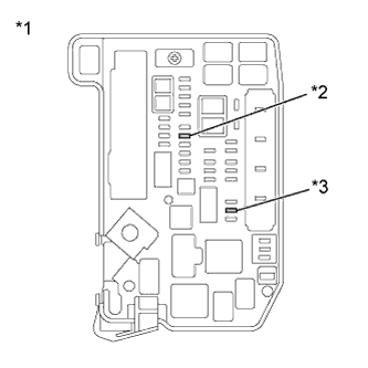
Text in Illustration *1 Engine Room Junction Block Assembly *2 AM2 Fuse *3 IGCT NO. 2 Fuse Remove the IGCT NO. 2 fuse and AM2 fuse from the engine room junction block assembly.
-
Disconnect connector E113 from the P position switch (transmission shift main switch).
-
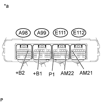
Text in Illustration *a Component with harness connected
(Power Management Control ECU)
Measure the resistance according to the value(s) in the table below.
Standard Resistance Tester Connection Switch Condition Specified Condition E111-16 (P1) - A98-2 (+B2) Power switch off 1.4 to 1.6 kΩ E111-16 (P1) - A99-5 (+B1) Power switch off 1.4 to 1.6 kΩ E111-16 (P1) - E111-1 (AM22) Power switch off 10 kΩ or higher E111-16 (P1) - E112-7 (AM21) Power switch off 10 kΩ or higher -
Connect the P position switch (transmission shift main switch) connector.
-
Install the IGCT NO. 2 fuse and AM2 fuse.
NG 
CHECK HARNESS AND CONNECTOR (SHORT TO POWER SUPPLY WIRES) Click here
OK
-
-
CHECK HARNESS AND CONNECTOR (POWER MANAGEMENT CONTROL ECU - P POSITION SWITCH)
-
Disconnect connector E111 from the power management control ECU.
-
Disconnect connector E113 from the P position switch (transmission shift main switch).
-
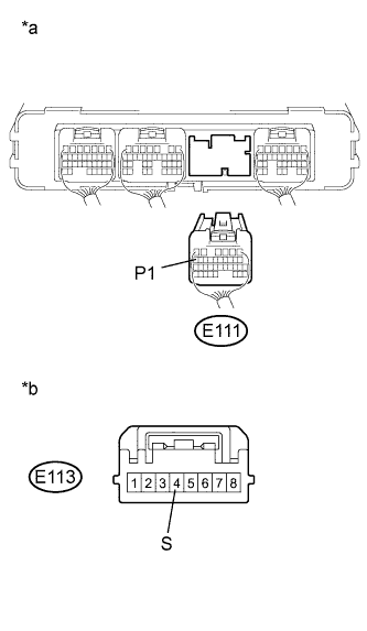
Text in Illustration *a Rear view of wire harness connector
(to Power Management Control ECU)
*b Front view of wire harness connector
(to P Position Switch (Transmission Shift Main Switch))
Measure the resistance according to the value(s) in the table below.
Standard Resistance (Check for Open) Tester Connection Switch Condition Specified Condition E111-16 (P1) - E113-4 (S) Power switch off Below 1 Ω Standard Resistance (Check for Short) Tester Connection Switch Condition Specified Condition E111-16 (P1) or E113-4 (S) - Body ground and other terminals Power switch off 10 kΩ or higher Tech Tips
As necessary, check that there is no short to power supply wires when performing the above wire harness inspection.
-
Connect the P position switch (transmission shift main switch) connector.
-
Connect the power management control ECU connector.
NG
REPAIR OR REPLACE HARNESS OR CONNECTOR
OK
-
-
CHECK HARNESS AND CONNECTOR (P POSITION SWITCH - BODY GROUND)
-
Disconnect connector E113 from the P position switch (transmission shift main switch).
-
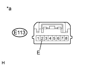
Text in Illustration *a Front view of wire harness connector
(to P Position Switch (Transmission Shift Main Switch))
Measure the resistance according to the value(s) in the table below.
Standard Resistance (Check for Open) Tester Connection Switch Condition Specified Condition E113-2 (E) - Body ground Power switch off Below 1 Ω -
Connect the P position switch (transmission shift main switch) connector.
NG
REPAIR OR REPLACE HARNESS OR CONNECTOR
OK 
REPLACE POWER MANAGEMENT CONTROL ECU Click here
-
-
CHECK HARNESS AND CONNECTOR (SHORT TO POWER SUPPLY WIRES)
-
Text in Illustration *1 Engine Room Junction Block Assembly *2 AM2 Fuse *3 IGCT NO. 2 Fuse Remove the IGCT NO. 2 fuse and AM2 fuse from the engine room junction block assembly.
-
Disconnect connector E113 from the P position switch (transmission shift main switch).
-
Disconnect all the connectors from the power management control ECU.
-
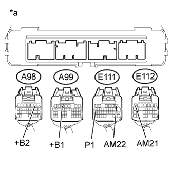
Text in Illustration *a Rear view of wire harness connector
(to Power Management Control ECU)
Measure the resistance according to the value(s) in the table below.
Standard Resistance Tester Connection Switch Condition Specified Condition E111-16 (P1) - A98-2 (+B2) Power switch off 10 kΩ or higher E111-16 (P1) - A99-5 (+B1) Power switch off 10 kΩ or higher E111-16 (P1) - E111-1 (AM22) Power switch off 10 kΩ or higher E111-16 (P1) - E112-7 (AM21) Power switch off 10 kΩ or higher -
Connect the power management control ECU connectors.
-
Connect the P position switch (transmission shift main switch) connector.
-
Install the IGCT NO. 2 fuse and AM2 fuse.
NG
REPAIR OR REPLACE HARNESS OR CONNECTOR
OK
REPLACE POWER MANAGEMENT CONTROL ECU Click here
-