ENGINE UNIT INSPECTION

-
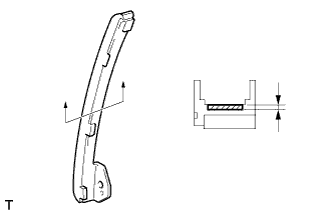
INSPECT NO. 1 VALVE ROCKER ARM SUB-ASSEMBLY
-
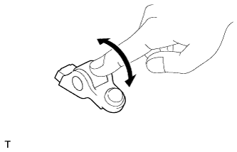
Turn the roller by hand to check that it turns smoothly.
If the roller does not turn smoothly, replace the No. 1 valve rocker arm sub-assembly.
-
-
INSPECT VALVE LASH ADJUSTER ASSEMBLY
Note
-
Keep the valve lash adjuster free from dirt and foreign matter.
-
Only use clean engine oil.
-
Place the lash adjuster into a container full of new engine oil.
-
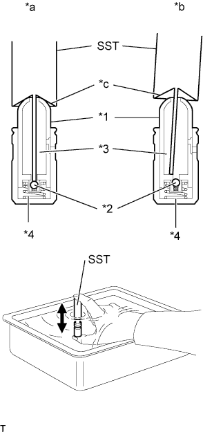
Text in Illustration *1 Plunger *2 Check Ball *3 Low Pressure Chamber *4 High Pressure Chamber *a CORRECT *b INCORRECT *c Taper Part Insert the tip of SST into the lash adjuster plunger and use the tip to press down on the check ball inside the plunger.
- SST
- 09276-75010
-
Squeeze SST and the valve lash adjuster together to move the plunger up and down 5 to 6 times.
-
Check the movement of the plunger and bleed the air.
OK Plunger moves up and down. Note
When bleeding high-pressure air from the compression chamber, make sure that the tip of SST is actually pressing the check ball as shown in the illustration. If the check ball is not pressed, air bleeding is not possible.
-
After bleeding the air, remove SST. Then try to quickly and firmly press the plunger with your fingers.
OK Plunger can be pressed 3 times. If the plunger can still be compressed after pressing it 3 times, replace the valve lash adjuster with a new one.
-
-
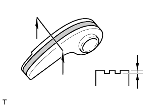
INSPECT CHAIN SUB-ASSEMBLY
-
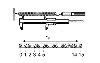
Text in Illustration *a Measurement Length Pull the chain with a force of 147 N (15 kgf, 33.0 lbf) as shown in the illustration.
-
Using a vernier caliper, measure the length of 15 links.
Maximum chain elongation 115.2 mm (4.54 in.) Note
Perform the measurement at 3 random places. Use the average of the measurements.
If the average elongation is more than the maximum, replace the chain sub-assembly.
-
-
INSPECT NO. 2 CHAIN SUB-ASSEMBLY
-
Text in Illustration *a Measurement Length Pull the chain with a force of 147 N (15 kgf, 33.0 lbf) as shown in the illustration.
-
Using a vernier caliper, measure the length of 15 links.
Maximum chain elongation 102.1 mm (4.02 in.) Note
Perform the measurement at 3 random places. Use the average of the measurements.
If the average elongation is more than the maximum, replace the No. 2 chain sub-assembly.
-
-
INSPECT OIL PUMP DRIVE GEAR
-
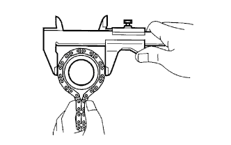
Place the chain around the oil pump drive gear.
-
Using a vernier caliper, measure the diameter of the oil pump drive gear and chain.
Minimum gear diameter (with chain) 48.2 mm (1.90 in.) Note
The vernier caliper must be in contact with the chain rollers when measuring.
If the diameter is less than the minimum, replace the chain and oil pump drive gear.
-
-
INSPECT OIL PUMP DRIVE SHAFT GEAR
-
Place the chain around the oil pump drive shaft gear.
-
Using a vernier caliper, measure the diameter of the oil pump drive shaft gear and chain.
Minimum gear diameter (with chain) 48.2 mm (1.90 in.) Note
The vernier caliper must be in contact with the chain rollers when measuring.
If the diameter is less than the minimum, replace the chain and oil pump drive shaft gear.
-
-
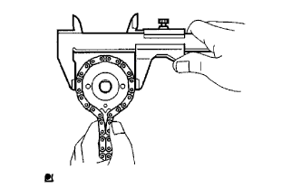
INSPECT CAMSHAFT TIMING GEAR ASSEMBLY
-
Place the chain around the camshaft timing gear assembly.
-
Using a vernier caliper, measure the diameter of the camshaft timing gear assembly and chain.
Minimum gear diameter (with chain) 96.8 mm (3.81 in.) Note
The vernier caliper must be in contact with the chain rollers when measuring.
If the diameter is less than the minimum, replace the chain and camshaft timing gear assembly.
-
-
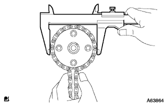
INSPECT CAMSHAFT TIMING SPROCKET
-
Place the chain around the camshaft timing sprocket.
-
Using a vernier caliper, measure the diameter of the camshaft timing sprocket and chain.
Minimum gear diameter (with chain) 96.8 mm (3.81 in.) Note
The vernier caliper must be in contact with the chain rollers when measuring.
If the diameter is less than the minimum, replace the chain and camshaft timing sprocket.
-
-
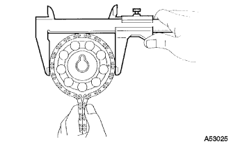
INSPECT CRANKSHAFT TIMING GEAR
-
Place the chain around the crankshaft timing gear.
-
Using a vernier caliper, measure the diameter of the crankshaft timing gear and chain.
Minimum gear diameter (with chain) 51.1 mm (2.01 in.) Note
The vernier caliper must be in contact with the chain rollers when measuring.
If the diameter is less than the minimum, replace the chain and crankshaft timing gear.
-
-
INSPECT CHAIN TENSIONER SLIPPER
-
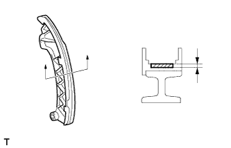
Using a vernier caliper, measure the chain tensioner slipper wear.
Maximum wear 1.0 mm (0.0394 in.) If the wear is more than the maximum, replace the chain tensioner slipper.
-
-
INSPECT NO. 1 CHAIN VIBRATION DAMPER
-
Using a vernier caliper, measure the No. 1 chain vibration damper wear.
Maximum wear 1.0 mm (0.0394 in.) If the wear is more than the maximum, replace the No. 1 chain vibration damper.
-
-
INSPECT NO. 2 CHAIN VIBRATION DAMPER
-
Using a vernier caliper, measure the No. 2 chain vibration damper wear.
Maximum wear 1.0 mm (0.0394 in.) If the wear is more than the maximum, replace the No. 2 chain vibration damper.
-
-
INSPECT CHAIN TENSIONER PLATE
-
Using a vernier caliper, measure the chain tensioner plate wear.
Maximum wear 1.0 mm (0.0394 in.) If the wear is more than the maximum, replace the chain tensioner plate.
-
-
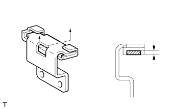
INSPECT NO. 1 CHAIN TENSIONER
-
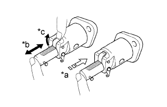
Text in Illustration *a Lock *b Move *c Raise Check that the plunger moves smoothly when the cam is raised with your finger.
-
Release the cam, then check that the plunger is locked in place by the cam and does not move when pushing with your finger.
If necessary, replace the No. 1 chain tensioner.
-
-
INSPECT CAMSHAFT
-
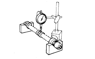
Inspect the camshaft for runout.
-
Place the camshaft on V-blocks.
-
Using a dial indicator, measure the circle runout at the center journal.
Maximum circle runout 0.04 mm (0.00157 in.) If the circle runout is more than the maximum, replace the camshaft.
-
-
Inspect the cam lobes.
-
Using a micrometer, measure the cam lobe height.
Standard cam lobe height 41.779 to 41.879 mm (1.6448 to 1.6488 in.) Minimum cam lobe height 41.629 mm (1.6389 in.) If the cam lobe height is less than the minimum, replace the camshaft.
-
-
Inspect the camshaft journals.
-
Using a micrometer, measure the journal diameter.
Standard Journal Diameter Journal Position Specified Condition No. 1 34.449 to 34.465 mm (1.3563 to 1.3569 in.) Other 22.949 to 22.965 mm (0.90350 to 0.90413 in.) If the journal diameter is not as specified, check the oil clearance Click here.
-
-
-
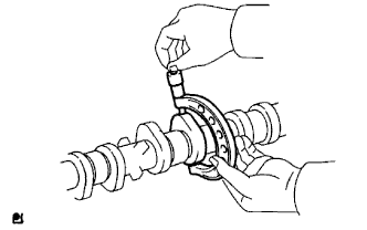
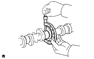
INSPECT NO. 2 CAMSHAFT
-
Inspect the No. 2 camshaft for runout.
-
Place the No. 2 camshaft on V-blocks.
-
Using a dial indicator, measure the circle runout at the center journal.
Maximum circle runout 0.04 mm (0.00157 in.) If the circle runout is more than the maximum, replace the No. 2 camshaft.
-
-
Inspect the cam lobes.
-
Using a micrometer, measure the cam lobe height.
Standard cam lobe height 43.346 to 43.446 mm (1.7065 to 1.7105 in.) Minimum cam lobe height 43.196 mm (1.7006 in.) If the cam lobe height is less than the minimum, replace the No. 2 camshaft.
-
-
Inspect the camshaft journals.
-
Using a micrometer, measure the journal diameter.
Standard Journal Diameter Journal Position Specified Condition No. 1 34.449 to 34.465 mm (1.3563 to 1.3569 in.) Other 22.949 to 22.965 mm (0.90350 to 0.90413 in.) If the journal diameter is not as specified, check the oil clearance Click here.
-
-
-
INSPECT CYLINDER HEAD SET BOLT
-
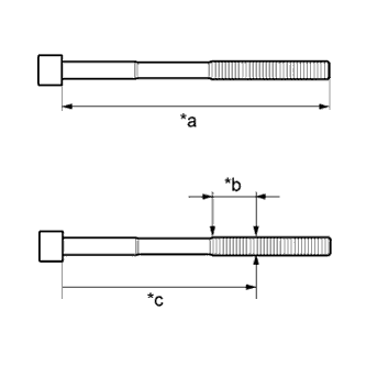
Text in Illustration *a Measurement Length *b Measurement Area *c Distance Using a vernier caliper, measure the length of the cylinder head set bolt from the seat to the end.
Standard length 146.8 to 148.2 mm (5.78 to 5.83 in.) Maximum length 149.2 mm (5.87 in.) Tech Tips
-
If the length is greater than the maximum, replace the bolt with a new one. Failure to do so may lead to engine damage.
-
If there is any thread deformation, replace the bolt with a new one.
-
-
Using a vernier caliper, measure the diameter of the threaded portion of the bolt at its thinnest point shown in the illustration.
Tech Tips
Use a straightedge to determine the thinnest point of the threaded portion of the bolt.
Measurement point 115 mm (4.53 in.) Standard diameter 9.77 to 9.96 mm (0.385 to 0.392 in.) Minimum diameter 9.4 mm (0.370 in.) Tech Tips
-
If the diameter is less than the minimum, replace the cylinder head set bolt with a new one. Failure to do so may lead to engine damage.
-
If there is any thread deformation, replace the cylinder head set bolt with a new one.
Tech Tips
If a visual check reveals no excessively thin areas, check the center of the bolt (refer to illustration) and find the area that has the smallest diameter.
-
-
-
INSPECT EXHAUST MANIFOLD
-
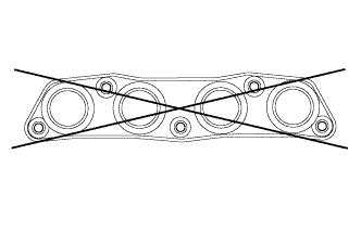
Using a precision straightedge and feeler gauge, measure the warpage on the surface that contacts the cylinder head.
Maximum warpage 0.7 mm (0.0276 in.) If the warpage is more than the maximum, replace the exhaust manifold.
-