AIR FUEL RATIO SENSOR INSTALLATION

-
INSTALL AIR FUEL RATIO SENSOR
-
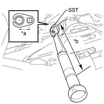
*a Fulcrum length 30 mm *b Fulcrum length 300 mm Using SST, install the air fuel ratio sensor.
- SST
- 09224-00010
- Torque:
- without SST
- 44 N*m { 449 kgf*cm, 32 ft.*lbf }
- with SST
- 40 N*m { 408 kgf*cm, 30 ft.*lbf }
Note
-
The "with SST" torque value is effective when using SST with a fulcrum length of 30 mm (1.18 in.).
-
The "with SST" torque value is effective when using a torque wrench with a fulcrum length of 300 mm (11.81 in.).
-
This torque value is effective when SST is parallel to the torque wrench.
-
Connect the air fuel ratio sensor connector and clamp.
-
-
INSTALL NO. 2 CYLINDER HEAD COVER
-
Engage the 3 clips to install the cover.
Note
-
Be sure to engage the clips securely.
-
Do not apply excessive force or hit the cover to engage the clips. This may cause the cover to break.
-
-
-
INSPECT FOR EXHAUST GAS LEAK
-
INSTALL OUTER COWL TOP PANEL SUB-ASSEMBLY (for LHD)
-
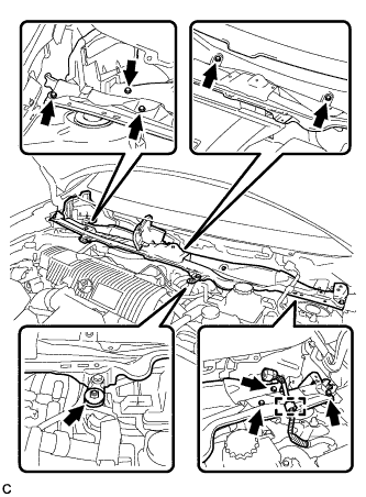
Install the outer cowl top panel with the 8 bolts and nut.
- Torque:
- Bolt
- 8.8 N*m { 90 kgf*cm, 78 in.*lbf }
- Nut
- 12 N*m { 122 kgf*cm, 9 ft.*lbf }
-
Engage the clamp.
-
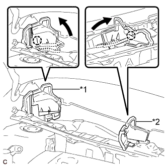
Text in Illustration *1 No. 1 Heater Air Duct Splash Shield Seal *2 Water Guard Plate RH Bend the No. 1 heater air duct splash shield seal and water guard plate RH, and engage each claw.
-
-
INSTALL OUTER COWL TOP PANEL SUB-ASSEMBLY (for RHD)
-
Install the outer cowl top panel with the 8 bolts and nut.
- Torque:
- Bolt
- 8.8 N*m { 90 kgf*cm, 78 in.*lbf }
- Nut
- 12 N*m { 122 kgf*cm, 9 ft.*lbf }
-
Engage the clamp of the wire harness.
-
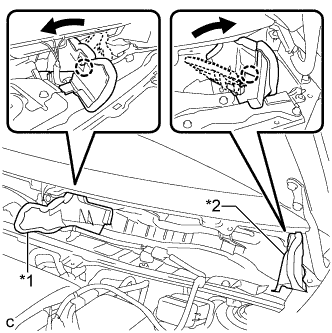
Text in Illustration *1 Water Guard Plate RH *2 No. 1 Heater Air Duct Splash Shield Seal Bend the water guard plate RH and No. 1 heater air duct splash shield seal, and engage each claw.
-
-
INSTALL COWL BODY MOUNTING REINFORCEMENT LH (for LHD)
-
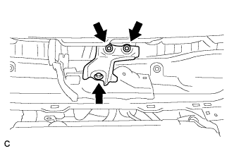
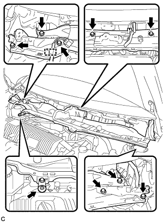
Install the cowl body mounting reinforcement LH with the 3 bolts.
- Torque:
- 8.8 N*m { 90 kgf*cm, 78 in.*lbf }
-
-
INSTALL COWL BODY MOUNTING REINFORCEMENT LH (for RHD)
-
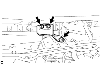
Install the cowl body mounting reinforcement LH with the 3 bolts.
- Torque:
- 8.8 N*m { 90 kgf*cm, 73 in.*lbf }
-
-
INSTALL WINDSHIELD WIPER MOTOR AND LINK