SFI SYSTEM, Diagnostic DTC:P0327, P0328
| DTC Code | DTC Name |
|---|---|
| P0327 | Knock Sensor 1 Circuit Low Input (Bank 1 or Single Sensor) |
| P0328 | Knock Sensor 1 Circuit High Input (Bank 1 or Single Sensor) |
DESCRIPTION
A flat type knock control sensor is used. Flat type knock control sensors (non-resonant type) have a structure that can detect vibrations over a wide band of frequencies: between approximately 6 kHz and 15 kHz.
Knock control sensors are fitted onto the engine block to detect engine knocking.
The knock control sensor contains a piezoelectric element which generates a voltage when it becomes deformed.
The voltage is generated when the engine block vibrates due to knocking. Occurrence of engine knocking can be suppressed by delaying the ignition timing.
| DTC No. | DTC Detection Condition | Trouble Area |
|---|---|---|
| P0327 | Output voltage of knock control sensor less than 0.5 V for 1 second or more (1 trip detection logic) |
|
| P0328 | Output voltage of knock control sensor more than 4.5 V for 1 second or more (1 trip detection logic) |
|
Tech Tips
When either DTC P0327 or P0328 is set, the ECM enters fail-safe mode. During fail-safe mode, the ignition timing is delayed to its maximum retardation. Fail-safe mode continues until the power switch is turned off.
Reference: Inspection using an oscilloscope
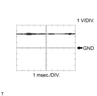
| Standard | ||||||||
|---|---|---|---|---|---|---|---|---|
|
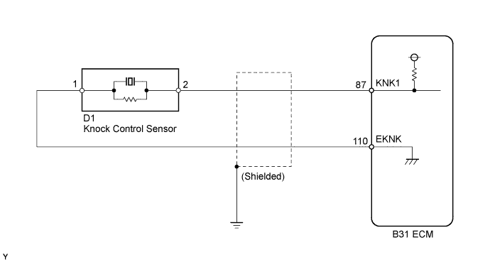
WIRING DIAGRAM
INSPECTION PROCEDURE
Tech Tips
Read freeze frame data using the intelligent tester. The ECM records vehicle and driving condition information as freeze frame data the moment a DTC is stored. When troubleshooting, freeze frame data can be helpful in determining whether the vehicle was running or stopped, whether the engine was warmed up or not, whether the air fuel ratio was lean or rich, as well as other data recorded at the time of a malfunction.
PROCEDURE
-
READ VALUE USING INTELLIGENT TESTER (KNOCK FEEDBACK VALUE)
-
Connect the intelligent tester to the DLC3.
-
Turn the power switch on (IG) and turn the tester on.
-
Put the engine in inspection mode Click here.
-
Start the engine.
-
Warm up the engine.
-
Enter the following menus: Powertrain / Engine and ECT / Knock Feedback Value.
-
Read the value while driving the vehicle.
OK The value changes. Tech Tips
Malfunction does not occur Knock Feedback Value changes Malfunctions occur Knock Feedback Value does not change The knock feedback value change can be confirmed by running the engine with a high load, for example, by activating the air conditioning system and racing the engine.
NG 
CHECK ECM (KNK1 VOLTAGE) Click here
OK 
CHECK FOR INTERMITTENT PROBLEMS Click here
-
-
CHECK ECM (KNK1 VOLTAGE)
-
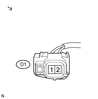
Text in Illustration *a Front view of wire harness connector
(to Knock Control Sensor)
Disconnect the knock control sensor connector.
-
Turn the power switch on (IG).
-
Measure the voltage according to the value(s) in the table below.
Standard Voltage Tester Connection Switch Condition Specified Condition D1-2 - D1-1 Power switch on (IG) 4.5 to 5.5 V -
Reconnect the knock control sensor connector.
NG
CHECK HARNESS AND CONNECTOR (ECM - KNOCK CONTROL SENSOR) Click here
OK 
-
-
INSPECT KNOCK CONTROL SENSOR
-
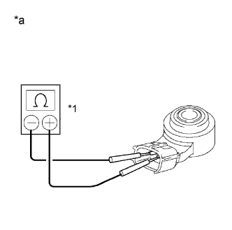
Text in Illustration *1 Ohmmeter *a Component without harness connected
(Knock Control Sensor)
Remove the knock control sensor Click here.
-
Measure the resistance according to the value(s) in the table below.
Standard Resistance Tester Connection Condition Specified Condition 1 - 2 20°C (68°F) 120 to 280 kΩ -
Reinstall the knock control sensor Click here.
NG 
REPLACE KNOCK CONTROL SENSOR Click here
OK
REPLACE ECM Click here
-
-
CHECK HARNESS AND CONNECTOR (ECM - KNOCK CONTROL SENSOR)
-
Disconnect the knock control sensor connector.
-
Disconnect the ECM connector.
-
Measure the resistance according to the value(s) in the table below.
Standard Resistance (Check for Open) Tester Connection Condition Specified Condition D1-2 - B31-87 (KNK1) Always Below 1 Ω D1-1 - B31-110 (EKNK) Always Below 1 Ω Standard Resistance (Check for Short) Tester Connection Condition Specified Condition D1-2 or B31-87 (KNK1) - Body ground Always 10 kΩ or higher D1-1 or B31-110 (EKNK) - Body ground Always 10 kΩ or higher -
Reconnect the knock control sensor connector.
-
Reconnect the ECM connector.
NG
REPAIR OR REPLACE HARNESS OR CONNECTOR (ECM - KNOCK CONTROL SENSOR)
OK
REPLACE ECM Click here
-