AUDIO AND VISUAL SYSTEM Radio Receiver Power Source Circuit
DESCRIPTION
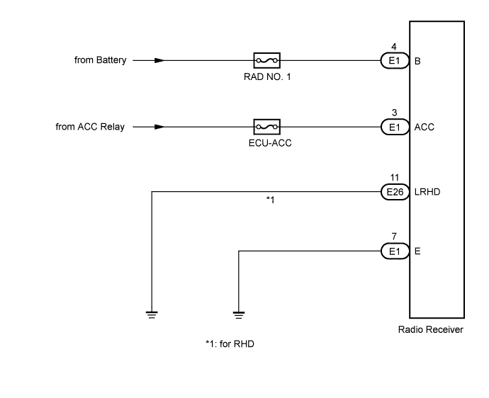
This circuit provides power to the radio receiver assembly.
WIRING DIAGRAM
INSPECTION PROCEDURE
PROCEDURE
-
INSPECT RADIO RECEIVER ASSEMBLY
-
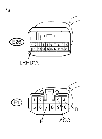
Text in Illustration *A for RHD *a Front view of wire harness connector
(to Radio Receiver Assembly)
Disconnect the radio receiver assembly connectors.
-
Measure the resistance according to the value in the table below.
Standard Resistance Tester Connection Condition Specified Condition E1-7 (E) - Body ground Always Below 1 Ω E26-11 (LRHD) - Body ground*1 Always Below 1 Ω
-
*1: for RHD
-
-
Measure the voltage according to the values in the table below.
Standard Voltage Tester Connection Condition Specified Condition E1-4 (B) - E1-7 (E) Power switch off 11 to 14 V E1-3 (ACC) - E1-7 (E) Power switch on (ACC) 11 to 14 V
NG 
REPAIR OR REPLACE HARNESS OR CONNECTOR
OK 
PROCEED TO NEXT SUSPECTED AREA SHOWN IN PROBLEM SYMPTOMS TABLE Click here
-