PARKING BRAKE LEVER INSTALLATION
-
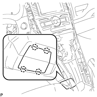
INSTALL PARKING BRAKE LEVER ASSEMBLY
-
Install the parking brake lever assembly with the 4 bolts.
- Torque:
- 15 N*m { 148 kgf*cm, 11 ft.*lbf }
-
Connect the parking brake switch connector.
-
Engage the wire harness clamp to the parking brake lever assembly.
-
-
CONNECT NO. 3 PARKING BRAKE CABLE ASSEMBLY
-
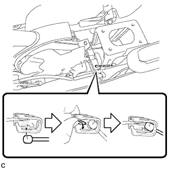
Connect the No. 3 parking brake cable assembly to the parking brake equalizer as shown in the illustration.
-
-
CONNECT NO. 2 PARKING BRAKE CABLE ASSEMBLY
Tech Tips
Perform the same procedure as for the No. 3 parking brake cable assembly.
-
ADJUST PARKING BRAKE LEVER TRAVEL
Note
Make sure that the brake lines have been bled and no air is present before performing parking brake adjustment.
-
Remove the rear console box cover Click here.
-
Completely release the parking brake lever.
-
Loosen the lock nut and adjusting nut to completely release the parking brake cable.
-
Strongly step on the brake pedal 3 to 5 times with the engine stopped.
-
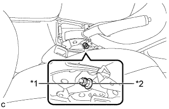
Text in Illustration *1 Lock Nut *2 Adjusting Nut Turn the adjusting nut until the parking brake lever travel is corrected to within the specified range.
Parking brake lever travel 4 to 7 notches at 200 N (20 kgf, 45 lbf) -
Tighten the lock nut.
- Torque:
- 6.0 N*m { 61 kgf*cm, 53 in.*lbf }
-
Operate the parking brake lever 3 to 4 times, and check the parking brake lever travel.
-
Check whether the parking brake drags or not.
-
Install the rear console box cover Click here.
-
-
INSPECT BRAKE WARNING LIGHT
-
When operating the parking brake lever, check that the brake warning light illuminates.
Standard The brake warning light always illuminates at the first click.
-
-
INSTALL LOWER NO. 2 INSTRUMENT PANEL FINISH PANEL
-
Engage the 2 clips and guide.
-
Install the lower No. 2 instrument panel finish panel with the 2 screws <E> or <F>.
-
-
INSTALL LOWER NO. 1 INSTRUMENT PANEL FINISH PANEL
-
Engage the 2 clips and guide.
-
Engage the 4 claws and 2 guides.
-
Install the lower No. 1 instrument panel finish panel with the 2 screws <E> or <F>.
-
-
INSTALL INSTRUMENT PANEL UNDER TRAY
-
Engage the 4 claws and install the instrument panel under tray.
-
-
INSTALL FRONT NO. 1 CONSOLE BOX INSERT
-
Engage the guide.
-
Engage the 3 claws and install the front No. 1 console box insert.
-
-
INSTALL FRONT NO. 2 CONSOLE BOX INSERT
-
Engage the guide.
-
Engage the 3 claws and install the front No. 2 console box insert.
-
-
INSTALL LOWER CENTER INSTRUMENT PANEL FINISH PANEL
-
Engage the 4 claws and 6 clips.
-
Install the lower center instrument panel finish panel with the 2 screws <E> or <F>.
-
-
INSTALL UPPER CONSOLE PANEL
-
Engage the 7 claws and install the upper console panel.
-
-
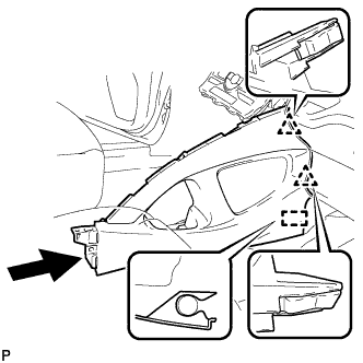
INSTALL INSTRUMENT PANEL FINISH PANEL END LH
-
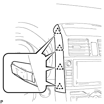
Engage the 4 clips and install the instrument panel finish panel end LH.
-
-
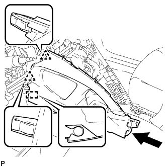
INSTALL INSTRUMENT PANEL FINISH PANEL END RH
-
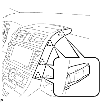
Engage the 4 clips and install the instrument panel finish panel end RH.
-
-
INSTALL INDOOR ELECTRICAL KEY OSCILLATOR