PARKING BRAKE LEVER REMOVAL
-
REMOVE INDOOR ELECTRICAL KEY OSCILLATOR
-
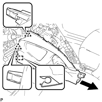
REMOVE INSTRUMENT PANEL FINISH PANEL END LH
-
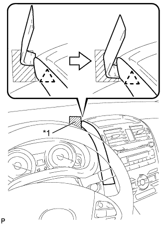
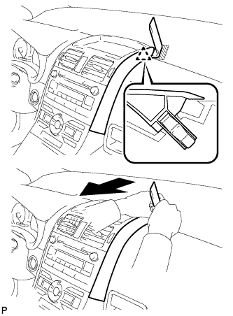
Text in Illustration *1 Protective Tape Apply protective tape to the area shown in the illustration.
-
Insert a roof moulding remover and slide the remover toward the clip.
-
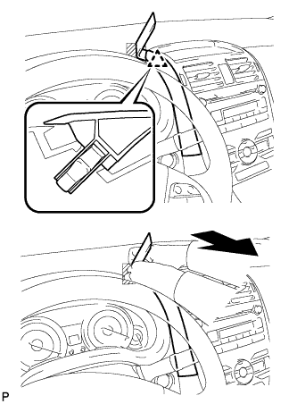
Pull the remover with both hands to disengage the clip as shown in the illustration.
-
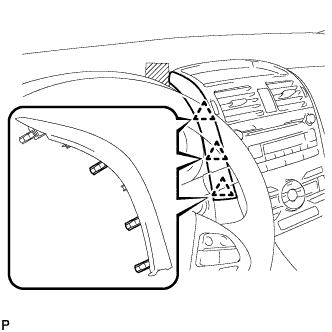
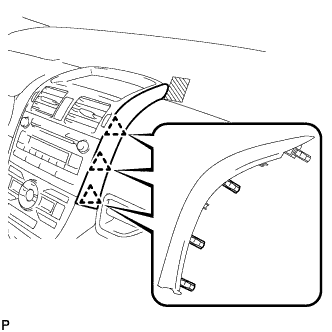
Disengage the 3 clips and remove the instrument panel finish panel end LH.
-
-
REMOVE INSTRUMENT PANEL FINISH PANEL END RH
-
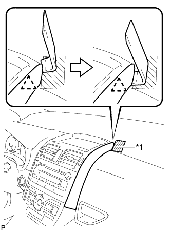
Text in Illustration *1 Protective Tape Apply protective tape to the area shown in the illustration.
-
Insert a roof moulding remover and slide the remover toward the clip.
-
Pull the remover with both hands to disengage the clip as shown in the illustration.
-
Disengage the 3 clips and remove the instrument panel finish panel end RH.
-
-
REMOVE UPPER CONSOLE PANEL
-
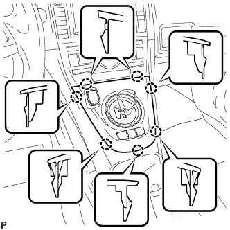
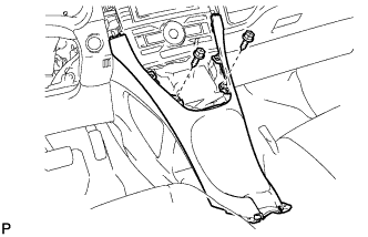
Disengage the 7 claws.
-
Disconnect the connector and remove the upper console panel.
-
-
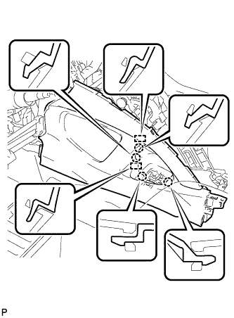
REMOVE LOWER CENTER INSTRUMENT PANEL FINISH PANEL
-
Remove the 2 screws <E> or <F>.
-
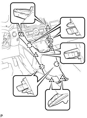
Disengage the 4 claws and 6 clips, and remove the lower center instrument panel finish panel.
-
-
REMOVE FRONT NO. 1 CONSOLE BOX INSERT
-
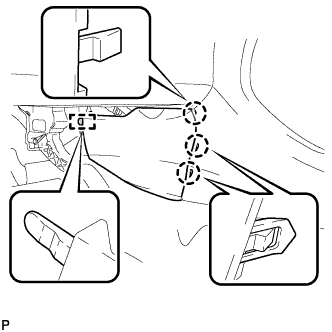
Disengage the 3 claws.
-
Disengage the guide and remove the front No. 1 console box insert.
-
-
REMOVE FRONT NO. 2 CONSOLE BOX INSERT
-
Disengage the 3 claws.
-
Disengage the guide and remove the front No. 2 console box insert.
-
-
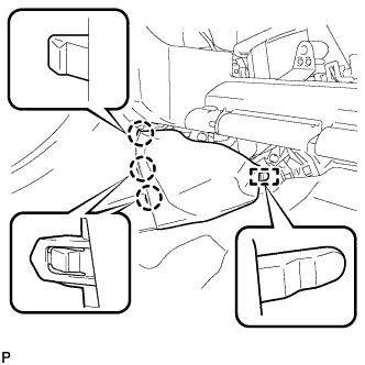
REMOVE INSTRUMENT PANEL UNDER TRAY
-

Text in Illustration *1 Protective Tape Using a screwdriver, disengage the 4 claws and remove the instrument panel under tray.
Tech Tips
Tape the screwdriver tip before use.
-
-
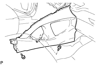
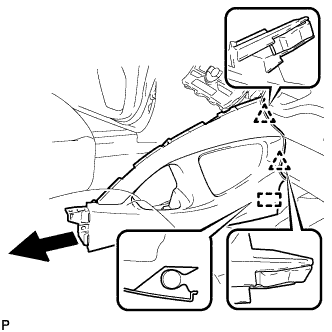
REMOVE LOWER NO. 1 INSTRUMENT PANEL FINISH PANEL
-
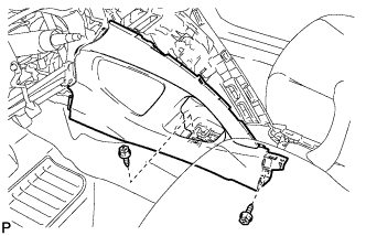
Remove the 2 screws <E> or <F>.
-
Disengage the 4 claws and 2 guides.
-
Disengage the 2 clips and guide, and remove the lower No. 1 instrument panel finish panel.
-
-
REMOVE LOWER NO. 2 INSTRUMENT PANEL FINISH PANEL
-
Remove the 2 screws <E> or <F>.
-
Disengage the 2 clips and guide, and remove the lower No. 2 instrument panel finish panel.
-
-
LOOSEN ADJUSTING NUT
-
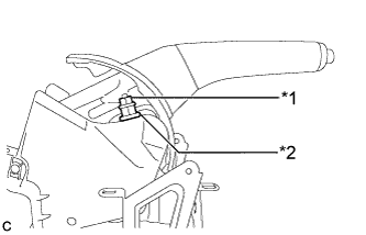
Text in Illustration *1 Lock Nut *2 Adjusting Nut Remove the lock nut.
-
Loosen the adjusting nut.
-
-
SEPARATE NO. 3 PARKING BRAKE CABLE ASSEMBLY
-
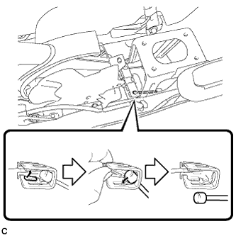
Separate the No. 3 parking brake cable assembly from the parking brake equalizer as shown in the illustration.
-
-
SEPARATE NO. 2 PARKING BRAKE CABLE ASSEMBLY
Tech Tips
Perform the same procedure as for the No. 3 parking brake cable assembly.
-
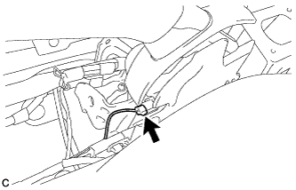
REMOVE PARKING BRAKE LEVER ASSEMBLY
-
Disengage the wire harness clamp from the parking brake lever assembly.
-
Disconnect the parking brake switch connector.
-
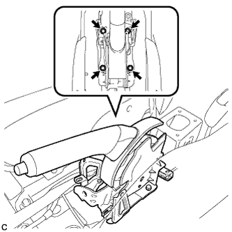
Remove the 4 bolts and the parking brake lever assembly.
-