REAR BRAKE FLEXIBLE HOSE INSTALLATION
Note
-
Because the left and right rear flexible hoses are not interchangeable, verify the part number when installing the flexible hoses.
-
If the hoses are to be reused, connect them after checking the identification marks placed when each hose was disconnected.
Tech Tips
-
Use the same procedure for the LH side and RH side.
-
The following procedure is for the LH side.
-
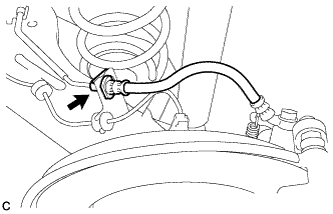
INSTALL REAR BRAKE TUBE FLEXIBLE HOSE (for LH Side)
-
Install the rear brake tube flexible hose with the bolt and a new clip.
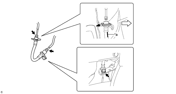
Text in Illustration *a Identification Mark - - 
Inside of the Vehicle - - - Torque:
- 19 N*m { 194 kgf*cm, 14 ft.*lbf }
Note
-
Install the clip as far as it will go.
-
When installing the rear brake tube flexible hose, face the identification mark to the inside of the vehicle and minimize twisting of the hose.
-
Using a union nut wrench, connect the 2 brake lines to the rear brake tube flexible hose.
- Torque:
- 15 N*m { 155 kgf*cm, 11 ft.*lbf }
Note
-
Do not bend or damage the brake line.
-
Do not allow any foreign matter such as dirt and dust to enter the brake line from the connecting points.
-
Use the formula to calculate special torque values for situations where the union nut wrench is combined with a torque wrench Click here.
-
-
INSTALL REAR BRAKE TUBE FLEXIBLE HOSE (for RH Side)
-
Install the rear brake tube flexible hose with 2 new clips.
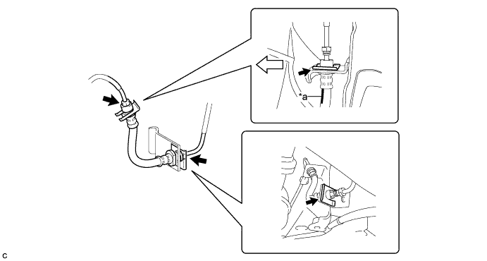
Text in Illustration *a Identification Mark - - Inside of the Vehicle - - Note
-
Install each clip as far as it will go.
-
When installing the rear brake tube flexible hose, face the identification mark to the inside of the vehicle and minimize twisting of the hose.
-
-
Using a union nut wrench, connect the 2 brake lines to the rear brake tube flexible hose.
- Torque:
- 15 N*m { 155 kgf*cm, 11 ft.*lbf }
Note
-
Do not bend or damage the brake line.
-
Do not allow any foreign matter such as dirt and dust to enter the brake line from the connecting points.
-
Use the formula to calculate special torque values for situations where the union nut wrench is combined with a torque wrench Click here.
-
-
INSTALL REAR FLEXIBLE HOSE
-
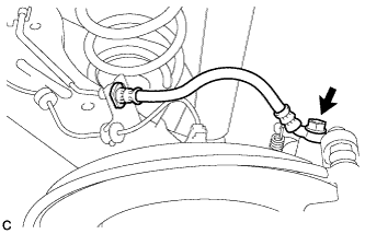
Connect the rear flexible hose to the rear disc brake cylinder assembly with the union bolt and a new gasket.
- Torque:
- 29 N*m { 296 kgf*cm, 21 ft.*lbf }
-
Install a new clip.
Note
Install the clip as far as it will go.
-
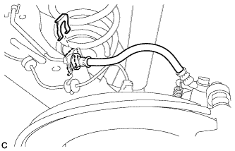
Using a union nut wrench, connect the brake line to the rear flexible hose while holding the rear flexible hose with a wrench.
- Torque:
- 15 N*m { 155 kgf*cm, 11 ft.*lbf }
Note
-
Do not bend or damage the brake line.
-
Do not allow any foreign matter such as dirt and dust to enter the brake line from the connecting points.
-
Use the formula to calculate special torque values for situations where the union nut wrench is combined with a torque wrench Click here.
-
-
FILL RESERVOIR WITH BRAKE FLUID
-
CONNECT CABLE TO NEGATIVE BATTERY TERMINAL
Note
When disconnecting the cable, some systems need to be initialized after the cable is reconnected Click here.
-
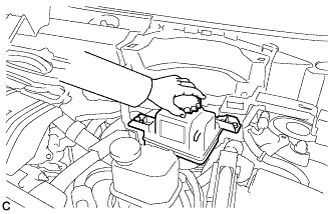
INSTALL BATTERY BOX COVER
-
Engage the 3 guides to install the battery box cover.
-
-
INSTALL REAR DECK FLOOR BOX
-
Install the rear deck floor box.
-
-
INSTALL REAR FLOOR MAT
-
Install the rear floor mat.
-
-
BLEED BRAKE LINE
-
Disengage the 5 claws and 3 guides to remove the center cowl top ventilator louver.
-
Bleed brake line.
-
Remove the brake master cylinder reservoir filler cap assembly.
-
Add brake fluid into the reservoir between MAX and MIN level on the brake fluid reservoir.
Brake fluid SAE J1703 or FMVSS No. 116 DOT3 SAE J1704 or FMVSS No. 116 DOT4 -
Connect the intelligent tester to the DLC3 and turn the power switch on (IG).
-
Turn the intelligent tester on and enter the following menus: Chassis / ABS/VSC/TRC / Air Bleeding.
-
Select "Usual air bleeding" on the intelligent tester display, and bleed air from the brake fluid following the instructions on the intelligent tester.
-
After air bleeding, tighten each bleeder plug.
- Torque:
- front bleeder plug (for 15 inch Front Brake)
- 12 N*m { 122 kgf*cm, 9 ft.*lbf }
- front bleeder plug (for 16 inch Front Brake)
- 8.3 N*m { 85 kgf*cm, 73 in.*lbf }
- rear bleeder plug
- 11 N*m { 112 kgf*cm, 8 ft.*lbf }
-
Clear the DTCs Click here.
-
Turn the intelligent tester off and turn the power switch off.
-
-
Inspect for brake fluid leaks.
-
Install the brake master cylinder reservoir filler cap.
-
Engage the 5 claws and 3 guides to install the center cowl top ventilator louver.
-
-
INSTALL REAR WHEEL
- Torque:
- 103 N*m { 1050 kgf*cm, 76 ft.*lbf }