BRAKE BOOSTER (for LHD) REMOVAL
-
REMOVE REAR FLOOR MAT
-
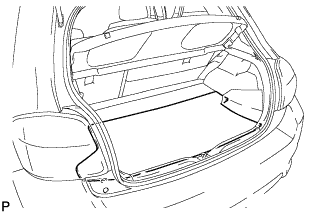
Remove the rear floor mat.
-
-
REMOVE REAR DECK FLOOR BOX
-
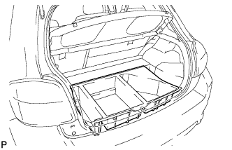
Remove the rear deck floor box.
-
-
REMOVE BATTERY BOX COVER
-
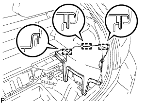
Disengage the 3 guides and remove the battery box cover.
-
-
DISABLE BRAKE CONTROL
-
Wait at least 2 minutes after the power switch off.
Note
When the brake pedal is depressed or the door courtesy switch is turned on even if the power switch is off, the brake control system activates. Therefore do not depress the brake pedal or open/close the doors until the reservoir level switch connector is disconnected.
-
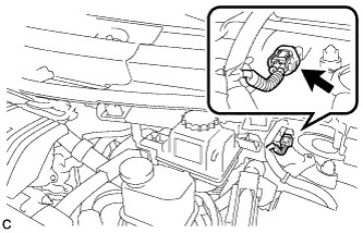
Disconnect the reservoir level switch connector with the parking brake applied.
-
Disconnect the cable from the negative (-) battery terminal.
Note
When disconnecting the cable, some systems need to be initialized after the cable is reconnected Click here.
-
Depress the brake pedal 40 times or more to return all the fluid in the accumulator back to the reservoir.
-
Check that the brake pedal can not be further depressed.
-
Release the parking brake.
-
-
REMOVE NO. 1 INSTRUMENT PANEL UNDER COVER SUB-ASSEMBLY
-
Remove the 2 screws <C> or <D>.
-
Disengage the claw and guide, and remove the No. 1 instrument panel under cover sub-assembly.
-
-
REMOVE WINDSHIELD WIPER MOTOR AND LINK ASSEMBLY
-
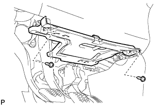
REMOVE COWL BODY MOUNTING REINFORCEMENT LH
-
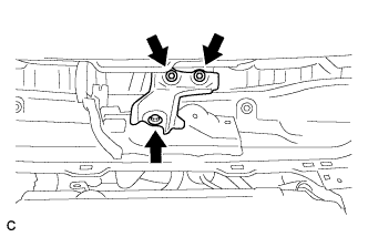
Remove the 3 bolts and cowl body mounting reinforcement LH.
-
-
REMOVE OUTER COWL TOP PANEL
-
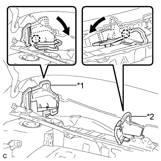
Text in Illustration *1 No. 1 Heater Air Duct Splash Shield Seal *2 Water Guard Plate RH Disengage each claw of the No. 1 heater air duct splash shield seal and water guard plate RH, and bend them.
-
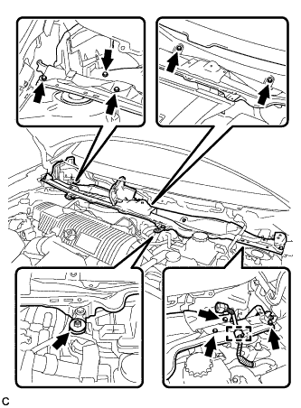
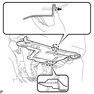
Disengage the clamp and separate the wire harness.
-
Remove the 8 bolts, nut and outer cowl top panel.
-
-
DRAIN BRAKE FLUID
Note
If brake fluid leaks onto any painted surface, immediately wash it off.
-
REMOVE BRAKE PEDAL RETURN SPRING
-
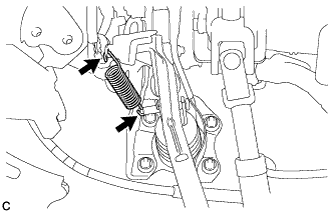
Remove the brake pedal return spring from the brake pedal support sub-assembly and push rod pin.
-
-
REMOVE PUSH ROD PIN
-
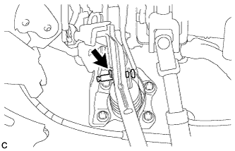
Remove the clip and push rod pin to separate the brake pedal sub-assembly from the push rod clevis.
-
-
SEPARATE BRAKE MASTER CYLINDER RESERVOIR WITH BRACKET
-
Disengage the clamp.
-
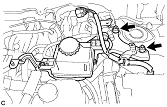
Remove the 2 nuts and separate the brake master cylinder reservoir with bracket.
-
-
DISCONNECT NO. 1 RESERVOIR HOSE
-
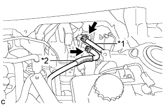
Text in Illustration *1 No. 1 Reservoir Hose *2 No. 2 Reservoir Hose Move the 2 clips and disconnect the No. 1 reservoir hose and No. 2 reservoir hose from the brake booster with master cylinder assembly.
-
-
DISCONNECT NO. 2 RESERVOIR HOSE
-
DISCONNECT BRAKE ACTUATOR HOSE
-
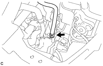
Move the clip and disconnect the brake actuator hose from the brake booster pump assembly.
-
-
REMOVE BRAKE MASTER CYLINDER RESERVOIR WITH BRACKET
-
REMOVE NO. 7 BRAKE ACTUATOR BRACKET
-
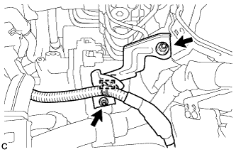
Disengage the clamp.
-
Remove the 2 nuts and No. 7 brake actuator bracket.
-
-
REMOVE BRAKE BOOSTER WITH MASTER CYLINDER ASSEMBLY
-
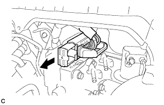
Release the lock lever and disconnect the connector from the brake booster with master cylinder assembly.
Note
Be careful not to allow any brake fluid to enter the removed connector.
Tech Tips
Perform this step only when the connector has not been disconnected.
-
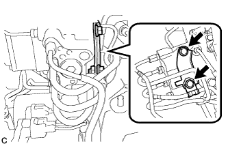
Remove the 2 bolts and No. 3 brake tube clamp bracket from the brake booster with master cylinder assembly.
-
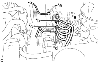
Using a union nut wrench, disconnect the 5 brake lines from the brake booster with master cylinder assembly.
-
Use tags or make a memo to identify the places to reconnect.
Text in Illustration *a to Front Wheel Cylinder LH *b to Rear Wheel Cylinder RH *c to Brake Booster Pump Assembly *d to Rear Wheel Cylinder LH *e to Front Wheel Cylinder RH -
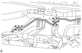
Disengage the 2 clamps and separate the brake line.
-
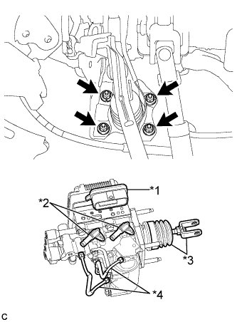
Text in Illustration *1 Connector Portion *2 Union *3 Push Rod Clevis and Boot *4 Front No. 2 Brake Tube Remove the 4 nuts and brake booster with master cylinder assembly.
Note
-
Do not kink or damage the brake lines.
-
Do not carry the brake booster with master cylinder assembly by the portion shown in the illustration.
-
-
-
REMOVE BRAKE BOOSTER GASKET