BRAKE PEDAL STROKE SENSOR INSTALLATION
-
INSTALL BRAKE PEDAL STROKE SENSOR ASSEMBLY
Note
Do not drop the brake pedal stroke sensor assembly. If the brake pedal stroke sensor assembly has been dropped, replace the brake pedal stroke sensor assembly with a new one.
-
When installing a new brake pedal stroke sensor assembly:
Note
Do not break the brake pedal stroke sensor assembly lever set pin before installing the brake pedal stroke sensor assembly with the nut.
-
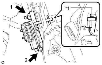
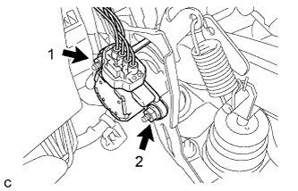
Text in Illustration *1 Brake Pedal Groove *2 Brake Pedal Stroke Sensor Assembly Lever Install the new brake pedal stroke sensor assembly to the brake pedal support assembly with the 2 nuts.
- Torque:
- 7.0 N*m { 71 kgf*cm, 62 in.*lbf }
Note
-
Engage the brake pedal stroke sensor assembly lever with the brake pedal groove.
-
Check that there is no foreign matter attached to the contact surface of the brake pedal stroke sensor assembly.
-
Check that the tip of the brake pedal stroke sensor assembly lever is protruding from the brake pedal groove.
-
Tighten the 2 nuts in the order shown in the illustration.
-
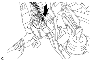
Connect the connector.
-
Firmly depress the brake pedal and break the brake pedal stroke sensor assembly lever set pin.
-
Remove the broken lever set pin.
-
-
When reusing the brake pedal stroke sensor assembly:
-
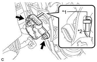
Text in Illustration *1 Brake Pedal Groove *2 Brake Pedal Stroke Sensor Assembly Lever Temporarily install the brake pedal stroke sensor assembly to the brake pedal support assembly with the 2 nuts.
Note
-
Engage the brake pedal stroke sensor assembly lever with the brake pedal groove.
-
Check that there is no foreign matter attached to the contact surface of the brake pedal stroke sensor assembly.
-
Check that the tip of the brake pedal stroke sensor assembly lever is protruding from the brake pedal groove.
-
-
-
-
ADJUST BRAKE PEDAL STROKE SENSOR ASSEMBLY
Note
When the brake pedal stroke sensor assembly is being reused, perform the following procedure to adjust it.
-
Connect the connector.
-
Connect the cable to the negative (-) battery terminal.
-
Connect the intelligent tester to the DLC3.
-
Turn the power switch on (IG).
-
Turn the intelligent tester on.
-
Enter the following menus: Chassis / ABS/VSC/ TRC / Data List.
-
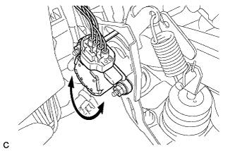
Reading the value of the brake pedal stroke sensor assembly shown in the Data List, turn the brake pedal stroke sensor assembly slowly to the right and left to adjust the output voltage to the range shown in the Normal Condition column of the following table.
Tester Display Measurement Item/
Range
Normal Condition Diagnostic Note Stroke Sensor Brake pedal stroke sensor /
0 to 5 V
0.8 to 1.2 V Brake pedal not depressed. -
Tighten the 2 nuts.
- Torque:
- 7.0 N*m { 71 kgf*cm, 62 in.*lbf }
Note
-
Do not depress the brake pedal after turning the power switch on (IG).
-
Tighten the 2 nuts in the order shown in the illustration.
-
Turn the power switch off.
-
Disconnect the intelligent tester.
-
Disconnect the cable from the negative battery terminal.
-
-
INSTALL DRIVER SIDE KNEE AIRBAG ASSEMBLY
-
CHECK AND CLEAR DTC
-
PERFORM INITIALIZATION AND CALIBRATION OF LINEAR SOLENOID VALVE