STEERING ANGLE SENSOR REMOVAL

Note
-
While the battery is connected, even if the power switch is off, the brake control system activates when the brake pedal is depressed or any door courtesy switch turns on. Therefore, when servicing brake system components, do not operate the brake pedal or open/close the doors while the battery is connected.
-
Do not replace the spiral cable with the battery connected and the power switch on (IG).
-
Do not rotate the spiral cable with the battery connected and the power switch on (IG).
-
Ensure that the steering wheel is installed and aligned straight when inspecting the steering angle sensor.
-
Do not remove the steering angle sensor from the spiral cable.
-
PRECAUTION
CAUTION:
Be sure to read Precaution thoroughly before servicing Click here.
-
TURN FRONT WHEELS TO FACE STRAIGHT AHEAD
-
REMOVE STEERING PAD
-
REMOVE STEERING WHEEL ASSEMBLY
-
Fully extend and tilt up the steering wheel.
-
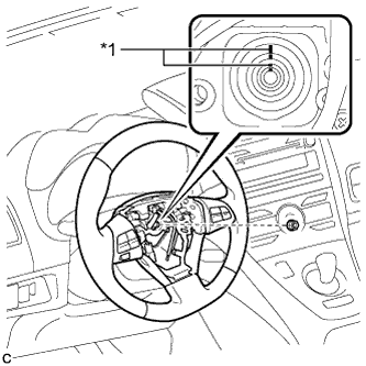
Text in Illustration *1 Matchmark Remove the steering wheel assembly set nut.
-
Put matchmarks on the steering wheel assembly and the steering main shaft.
-
Disconnect the connectors from the spiral cable.
-
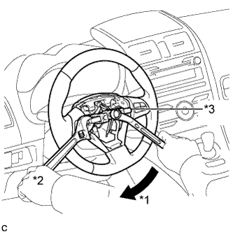
Text in Illustration *1 Turn *2 Hold *3 SST Using SST, remove the steering wheel assembly.
- SST
- 09950-50013 ( 09951-05010, 09952-05010, 09953-05020, 09954-05070 )
Note
Apply a small amount of grease to the threads and tip of SST (center bolt) before use.
-
-
REMOVE LOWER STEERING COLUMN COVER
Note
Removing the lower steering column cover in the incorrect order will cause the lower steering column cover to break.
-
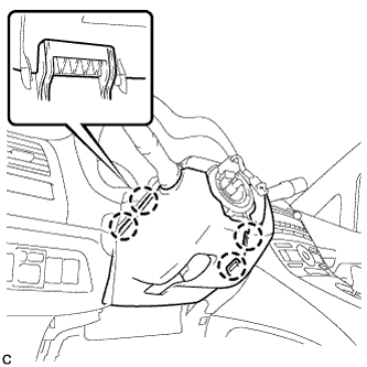
Push the right and left sides of the lower steering column cover, and disengage the 4 claws.
-
Insert fingers into the opening of the tilt lever of the lower steering column cover to disengage the 2 claws.
Tech Tips
Spread the claw to disengage it.
-
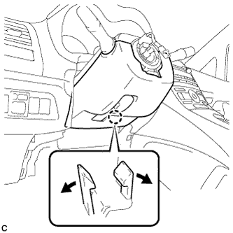
Using a screwdriver, insert the tip into each service hole to disengage the 2 claws to remove the lower steering column cover as shown in the illustration.
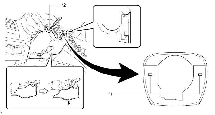
Text in Illustration *1 Service Hole *2 Protective Tape Tech Tips
Tape the screwdriver tip before use.
-
-
REMOVE UPPER STEERING COLUMN COVER
-
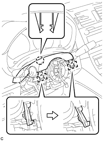
Disengage the 2 claws and 2 pins to remove the upper steering column cover.
-
-
REMOVE SPIRAL CABLE WITH SENSOR SUB-ASSEMBLY
Note
-
Do not replace the spiral cable with the battery connected and the power switch on (IG).
-
Do not rotate the spiral cable with the battery connected and the power switch on (IG).
-
Ensure that the steering wheel is installed and aligned straight when inspecting the steering sensor.
-
Do not remove the steering sensor from the spiral cable.
-
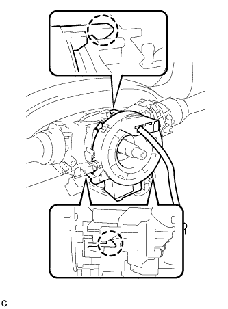
Disconnect the connectors from the spiral cable with sensor sub-assembly.
Note
When disconnecting any airbag connector, take care not to damage the airbag wire harness.
-
Disengage the 3 claws and remove the spiral cable with sensor sub-assembly.
-