REAR SPEED SENSOR INSTALLATION
Tech Tips
-
Use the same procedure for the RH side and LH side.
-
The procedure listed below is for the LH side.
-
The sensor rotor is a component of the rear axle hub and bearing assembly. If the sensor rotor needs to be replaced, replace the rear axle hub and bearing assembly.
-
The rear speed sensor is a component of the rear axle hub and bearing assembly. If the sensor malfunctions, replace the rear axle hub and bearing assembly.
-
INSTALL REAR AXLE HUB AND BEARING ASSEMBLY
-
Install the rear axle hub and bearing assembly and rear disc brake dust cover to the rear axle beam assembly with 4 new bolts.
- Torque:
- 90 N*m { 918 kgf*cm, 66 ft.*lbf }
Note
The 4 bolts cannot be reused after removal. Use 4 new bolts when installing.
-
-
INSPECT REAR AXLE HUB BEARING LOOSENESS
-
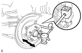
Using a dial indicator, check for looseness near the center of the axle hub.
Maximum looseness 0.05 mm (0.00196 in.) Note
-
Ensure that the dial indicator is set perpendicular to the measurement surface.
-
Keep the magnet of the dial indicator away from the rear axle hub and bearing (rear speed sensor).
Tech Tips
If the looseness exceeds the maximum, replace the rear axle hub and bearing assembly.
-
-
-
INSPECT REAR AXLE HUB RUNOUT
-
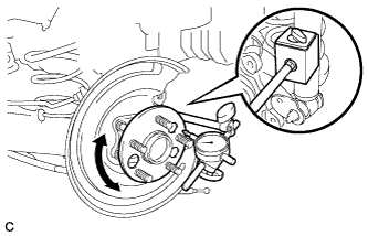
Using a dial indicator, check for runout on the surface of the axle hub outside the rear axle hub bolt.
Maximum runout 0.05 mm (0.00196 in.) Note
-
Ensure that the dial indicator is set perpendicular to the measurement surface.
-
Make sure to install the tip of the dial indicator towards the outside of the rear axle hub bolt.
-
Keep the magnet of the dial indicator away from the rear axle hub and bearing (rear speed sensor).
Tech Tips
If the runout exceeds the maximum, replace the rear axle hub and bearing assembly.
-
-
-
INSTALL REAR DISC
-
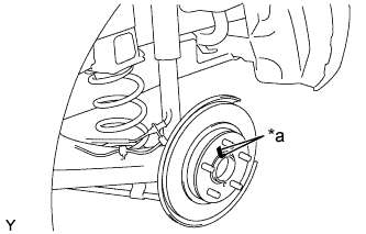
Text in Illustration *5 Matchmark Align the matchmarks of the disc and axle hub, and install the disc.
Note
When replacing the disc with a new one, select the installation position where the rear disc has minimal runout.
-
-
INSTALL REAR DISC BRAKE CALIPER ASSEMBLY
-
Install the rear disc brake caliper assembly with the 2 bolts.
- Torque:
- 57 N*m { 585 kgf*cm, 42 ft.*lbf }
-
-
INSTALL NO. 3 PARKING BRAKE CABLE ASSEMBLY
-
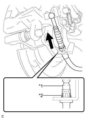
Text in Illustration *1 No. 3 Parking Brake Cable Assembly *2 Clip Install the No. 3 parking brake cable assembly to the rear disc brake cylinder assembly.
Tech Tips
Be sure to engage the No. 3 parking brake cable assembly clip onto the rear disc brake cylinder assembly as shown in the illustration.
-
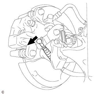
Connect the No. 3 parking brake cable assembly to the rear disc brake cylinder assembly.
-
-
CONNECT REAR SPEED SENSOR WIRE
-
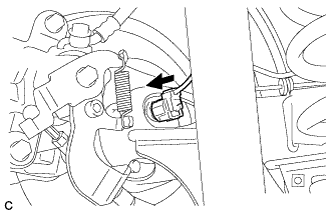
Connect the rear speed sensor wire connector.
-
-
ADJUST PARKING BRAKE LEVER TRAVEL
Note
Make sure that the brake lines have been bled and no air is present before performing parking brake adjustment.
-
Remove the rear console box cover Click here.
-
Completely release the parking brake lever.
-
Loosen the lock nut and adjusting nut to completely release the parking brake cable.
-
Strongly step on the brake pedal 3 to 5 times with the engine stopped.
-
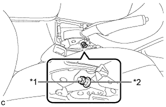
Text in Illustration *1 Lock Nut *2 Adjusting Nut Turn the adjusting nut until the parking brake lever travel is corrected to within the specified range.
Parking brake lever travel 4 to 7 notches at 200 N (20 kgf, 45 lbf) -
Tighten the lock nut.
- Torque:
- 6.0 N*m { 61 kgf*cm, 53 in.*lbf }
-
Operate the parking brake lever 3 to 4 times, and check the parking brake lever travel.
-
Check whether the parking brake drags or not.
-
Install the rear console box cover Click here.
-
-
INSPECT REAR DISC BRAKE CYLINDER OPERATION LEVER AND STOPPER CLEARANCE
-
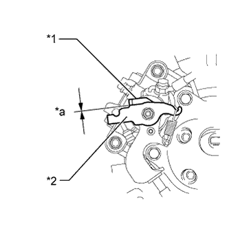
Text in Illustration *1 Stopper *2 Operation Lever *a 0.5 mm (0.02 in.) or less Release the parking brake lever and check that the clearance measurement between the rear disc brake cylinder operation lever and the stopper is within the specified range.
Clearance 0.5 mm (0.02 in.) or less If the clearance is not within the specified range, replace the rear disc brake caliper assembly.
-
-
INSTALL REAR CONSOLE BOX COVER
-
Connect the connector.
-
Engage the 2 guides and 4 clips to install the rear console box cover.
-
-
INSTALL REAR WHEEL
- Torque:
- 103 N*m { 1050 kgf*cm, 76 ft.*lbf }
-
CONNECT CABLE TO NEGATIVE BATTERY TERMINAL
-
Connect the cable to the negative (-) battery terminal.
Note
When disconnecting the cable, some systems need to be initialized after the cable is reconnected Click here.
-
Connect the reservoir level switch connector.
-
Clear the DTCs Click here.
-
-
INSTALL BATTERY BOX COVER
-
Engage the 3 guides to install the battery box cover.
-
-
INSTALL REAR DECK FLOOR BOX
-
Install the rear deck floor box.
-
-
INSTALL REAR FLOOR MAT
-
Install the rear floor mat.
-
-
CHECK FOR SPEED SENSOR SIGNAL