REAR COIL SPRING REMOVAL
-
REMOVE REAR WHEELS
-
REMOVE REAR FLOOR SIDE MEMBER COVER LH
-
Remove the nut, 2 bolts and rear floor side member cover LH.
-
-
REMOVE REAR FLOOR SIDE MEMBER COVER RH
Tech Tips
Perform the same procedure as the LH side.
-
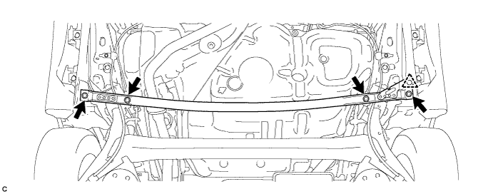
REMOVE REAR FLOOR SIDE MEMBER BRACE SUB-ASSEMBLY
-
Remove the 4 bolts.
-
Disengage the clip and remove the rear floor side member brace sub-assembly.
-
-
DISCONNECT REAR SPEED SENSOR WIRE (for LH Side)
-
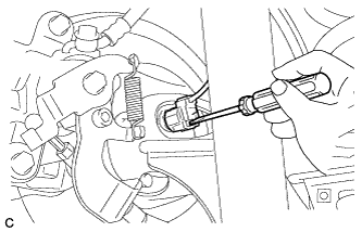
Using a screwdriver, disconnect the connector from the rear speed sensor.
Note
Be careful not to damage the rear speed sensor.
-
-
DISCONNECT REAR SPEED SENSOR WIRE (for RH Side)
Tech Tips
Perform the same procedure as the LH side.
-
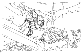
SEPARATE REAR SPEED SENSOR WIRE (for LH Side)
-
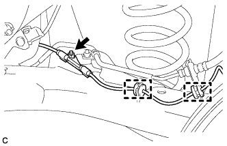
Remove the nut and separate the 2 clamps and rear speed sensor wire.
-
-
SEPARATE REAR SPEED SENSOR WIRE (for RH Side)
Tech Tips
Perform the same procedure as the LH side.
-
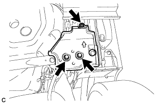
REMOVE REAR HEIGHT CONTROL SENSOR SUB-ASSEMBLY (w/ Height Control Sensor)
-
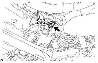
Disconnect the connector and disengage the clamp.
-
Remove the 3 bolts and the rear height control sensor sub-assembly.
-
-
SEPARATE REAR WHEEL HOUSE LINER LH
-
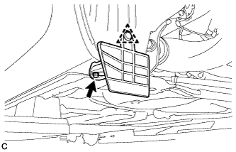
Remove the screw, clip and rear wheel house front plate LH.
-
Turn back the rear wheel house liner LH.
-
-
SEPARATE REAR WHEEL HOUSE LINER RH
Tech Tips
Perform the same procedure as the LH side.
-
REMOVE REAR COIL SPRING LH
-
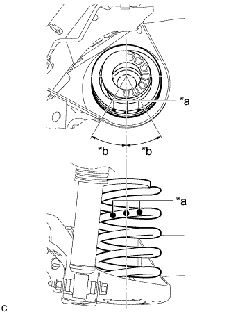
Text in Illustration *a Identification Mark *b 30° or less Check the identification marks on the rear coil spring LH.
Note
-
When reusing the rear coil spring, make sure that the identification marks are at the position as shown in the illustration..
-
If the identification marks have come off, apply new paint at the position shown in the illustration.
-
-
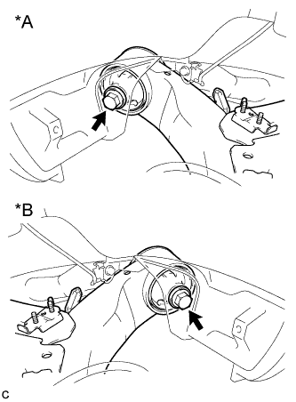
Text in Illustration *A LH Side *B RH Side Loosen the 2 bolts.
Note
Do not remove the bolts.
-
Support the spring seats of the rear axle beam assembly using 2 jacks and 2 wooden blocks.
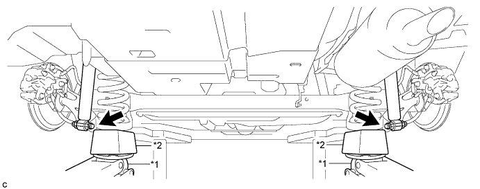
Text in Illustration *1 Jack *2 Wooden Block CAUTION:
Do not jack up the rear axle beam assembly too high as the vehicle may fall.
Tech Tips
Support the rear shock absorber at a position where it compresses by approximately 20 to 30 mm (0.787 to 1.18 in.).
-
Remove the 2 bolts while holding the 2 nuts and separate the rear axle beam assembly from the rear shock absorber assemblies LH and RH.
Note
Since stopper nuts are used, turn the bolts.
-
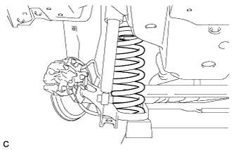
Slowly lower the rear axle beam assembly using 2 jacks and 2 wooden blocks, and remove the rear coil spring LH.
Note
When moving the rear axle beam assembly beyond full rebound, make sure that the rear axle beam assembly is not out of position for more than 10 minutes.
-
Slowly jack up the rear axle beam assembly using 2 jacks and 2 wooden blocks, and temporarily tighten the rear axle beam assembly to the rear shock absorber assemblies LH and RH with the 2 bolts and 2 nuts.
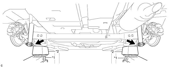
Text in Illustration *1 Jack *2 Wooden Block Note
Since stopper nuts are used, turn the bolts.
-
-
REMOVE REAR COIL SPRING RH
Tech Tips
Perform the same procedure as the LH side.
-
REMOVE REAR UPPER COIL SPRING INSULATOR LH
-
REMOVE REAR UPPER COIL SPRING INSULATOR RH
-
REMOVE REAR LOWER COIL SPRING INSULATOR LH
-
REMOVE REAR LOWER COIL SPRING INSULATOR RH