REAR SHOCK ABSORBER REMOVAL
Tech Tips
-
Use the same procedure for the RH side and LH side.
-
The procedure listed below is for the LH side.
-
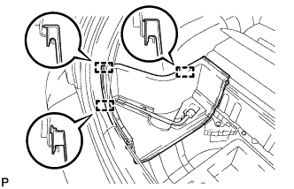
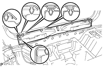
REMOVE PACKAGE TRAY TRIM PANEL ASSEMBLY
-
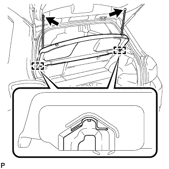
Disengage the 2 suspenders.
-
Disengage the 2 pins and remove the package tray trim panel assembly.
-
-
REMOVE REAR FLOOR MAT
-
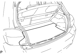
Remove the rear floor mat.
-
-
REMOVE REAR DECK FLOOR BOX
-
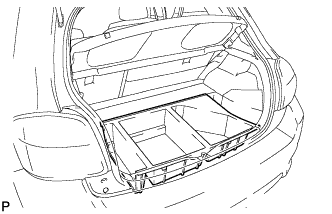
Remove the rear deck floor box.
-
-
REMOVE BATTERY BOX COVER
-
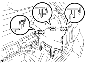
Disengage the 3 guides and remove the battery box cover.
-
-
REMOVE DECK FLOOR BOX LH
-
Disengage the 3 guides and remove the deck floor box LH.
-
-
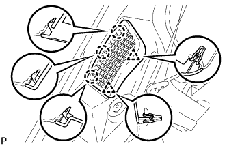
REMOVE DECK BOARD SUB-ASSEMBLY
-
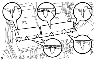
Disengage the 3 claws and 3 clips, and remove the deck board sub-assembly.
-
-
REMOVE NO. 6 BATTERY CARRIER PANEL
-
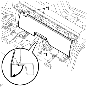
Text in Illustration *1 Double-sided Tape Remove the No. 6 battery carrier panel as shown in the illustration.
-
-
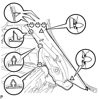
REMOVE REAR NO. 1 FLOOR BOARD
-
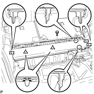
Remove the bolt.
-
Disengage the 2 claws, 2 clips and 3 guides, and remove the rear No. 1 floor board.
-
-
REMOVE REAR DECK TRIM COVER
-
Disengage the 10 claws and remove the rear deck trim cover.
-
-
REMOVE REAR SEAT ASSEMBLY LH (for LH Side)
-
REMOVE REAR SEAT ASSEMBLY RH (for RH Side)
-
REMOVE REAR DOOR SCUFF PLATE LH (for LH Side)
-
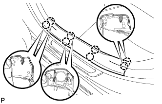
Disengage the 8 claws and remove the rear door scuff plate LH.
-
-
REMOVE REAR DOOR SCUFF PLATE RH (for RH Side)
Tech Tips
Perform the same procedure as the LH side.
-
REMOVE REAR DOOR OPENING TRIM WEATHERSTRIP LH (for LH Side)
-
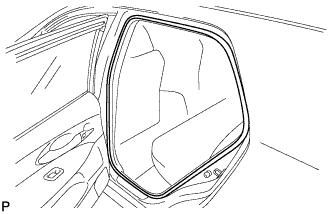
Remove the rear door opening trim weatherstrip LH.
-
-
REMOVE REAR DOOR OPENING TRIM WEATHERSTRIP RH (for RH Side)
Tech Tips
Perform the same procedure as the LH side.
-
REMOVE REAR SEATBACK HINGE SUB-ASSEMBLY (for LH Side)
-
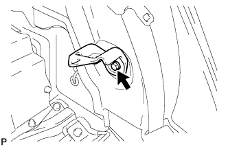
Remove the bolt and rear seatback hinge sub-assembly.
-
-
REMOVE REAR SEATBACK HINGE SUB-ASSEMBLY (for RH Side)
Tech Tips
Perform the same procedure as the LH side.
-
REMOVE REAR SEAT SIDE GARNISH LH (for LH Side)
-
Disengage the 6 claws and 2 clips, and remove the rear seat side garnish LH.
-
-
REMOVE REAR SEAT SIDE COVER RH (for RH Side)
-
Disengage the 3 claws and 2 clips, and remove the rear seat side cover RH.
-
-
REMOVE REAR SEAT SIDE GARNISH RH (for RH Side)
-
Disengage the 6 claws and 2 clips, and remove the rear seat side garnish RH.
-
-
REMOVE NO. 2 ROOM LIGHT ASSEMBLY (for LH Side)
-
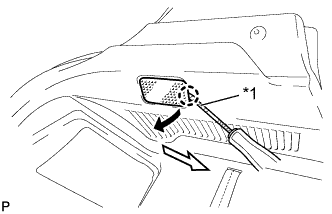
Text in Illustration *1 Protective Tape Using a screwdriver, disengage the claw.
Tech Tips
Tape the screwdriver tip before use.
-
Disconnect the connector and remove the No. 2 room light assembly.
-
-
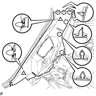
REMOVE SIDE DECK TRIM PANEL ASSEMBLY LH (for LH Side)
-
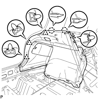
Disengage the 2 claws and 4 clips, and remove the side deck trim panel assembly LH.
-
-
REMOVE SIDE DECK TRIM PANEL ASSEMBLY RH (for RH Side)
-
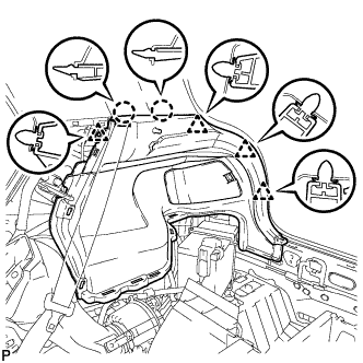
Disengage the 2 claws and 4 clips, and remove the side deck trim panel assembly LH.
-
-
REMOVE REAR WHEEL
-
REMOVE REAR HEIGHT CONTROL SENSOR SUB-ASSEMBLY (w/ Height Control Sensor)
-
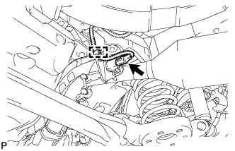
Disconnect the connector and disengage the clamp.
-
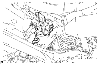
Remove the 3 bolts and the rear height control sensor sub-assembly.
-
-
REMOVE REAR SHOCK ABSORBER CUSHION RETAINER
-
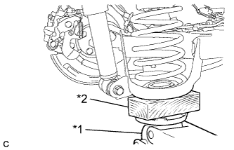
Text in Illustration *1 Jack *2 Wooden Block Support the spring seat of the rear axle beam assembly using a jack and wooden block.
CAUTION:
Do not jack up the rear axle beam assembly too high as the vehicle may fall.
Note
Keep supporting the rear axle beam assembly with a jack until the installation of the rear shock absorber assembly has been completed.
Tech Tips
Support the rear shock absorber at a position where it compresses by approximately 20 to 30 mm (0.787 to 1.18 in.).
-
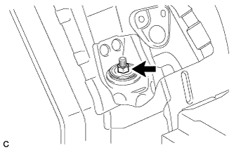
Using a hexagon socket wrench, secure the rear shock absorber rod and remove the lock nut.
Note
Securely insert the hexagon socket wrench to the rear shock absorber rod to prevent damage to the rear shock absorber assembly when removing the nut.
-
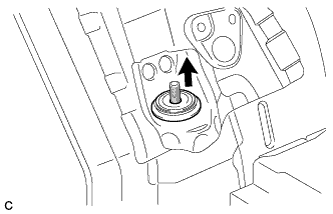
Remove the rear shock absorber cushion retainer.
-
-
REMOVE REAR SUSPENSION SUPPORT
-
Remove the rear suspension support.
-
-
REMOVE REAR SHOCK ABSORBER ASSEMBLY
-
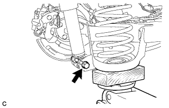
Remove the bolt while holding the nut and remove the rear shock absorber assembly.
Note
Since a stopper nut is used, turn the bolt.
-
-
REMOVE REAR NO. 1 SPRING BUMPER
-
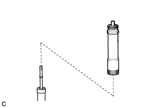
Remove the rear No. 1 spring bumper from the rear shock absorber assembly.
-
-
REMOVE REAR SUSPENSION SUPPORT
-
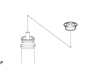
Remove the rear suspension support from the rear No. 1 spring bumper.
-