FRONT SHOCK ABSORBER INSTALLATION

Tech Tips
-
Use the same procedure for the RH side and LH side.
-
The procedure listed below is for the LH side.
-
SECURE FRONT SHOCK ABSORBER ASSEMBLY
-
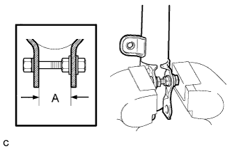
Install the bolt and nut to the front shock absorber assembly as shown in the illustration and secure the front shock absorber assembly in a vise.
Standard length A 28 mm (1.10 in.)
-
-
INSTALL FRONT COIL SPRING LOWER INSULATOR
-
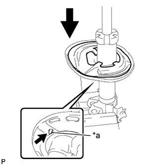
Text in Illustration *a Positioning Pin Install the front coil spring lower insulator.
Note
When installing the insulator, fit the insulator to the depression of the spring seat and align the positioning pin into the hole.
-
-
INSTALL FRONT SPRING BUMPER
-
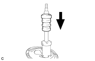
Install the front spring bumper to the front shock absorber assembly.
Note
Face the smaller diameter end of the front spring bumper downward.
-
-
INSTALL FRONT COIL SPRING
-
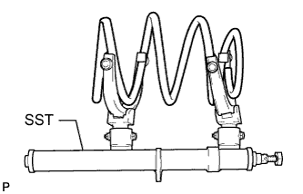
Using SST, compress the front coil spring.
- SST
- 09727-30021 ( 09727-00010, 09727-00021, 09727-00031 )
Note
Do not use an impact wrench. It will damage SST.
Tech Tips
If the front coil spring is compressed at an angle, using 2 SST will make the work easier
-
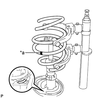
Text in Illustration *a Paint Mark Install the front coil spring.
Note
-
Make sure that the end of the front coil spring is positioned in the depression of the lower spring seat.
-
Make sure to install the coil spring with the paint mark facing downward.
-
-
-
INSTALL FRONT COIL SPRING UPPER INSULATOR
-
INSTALL FRONT COIL SPRING UPPER SEAT
-
INSTALL FRONT SUSPENSION SUPPORT DUST SEAL
-
INSTALL FRONT SUSPENSION SUPPORT SUB-ASSEMBLY
-
TEMPORARILY TIGHTEN FRONT SUPPORT TO FRONT SHOCK ABSORBER NUT
-
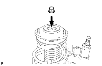
Temporarily tighten a new front support to front shock absorber nut.
-
Remove SST from the front coil spring.
Note
Do not use an impact wrench. It will damage SST.
-
-
INSTALL FRONT SHOCK ABSORBER WITH COIL SPRING
-
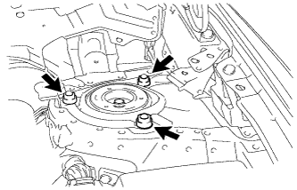
Install the front shock absorber with coil spring (upper side) with the 3 nuts.
- Torque:
- 50 N*m { 510 kgf*cm, 37 ft.*lbf }
-
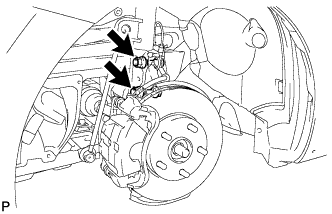
Install the front shock absorber with coil spring (lower side) to the steering knuckle with the 2 bolts and 2 nuts.
- Torque:
- 240 N*m { 2447 kgf*cm, 177 ft.*lbf }
Note
-
While keeping the bolts from rotating, tighten the nuts.
-
Keep the contact surfaces of the steering knuckle and shock absorber free of grease and foreign matter.
-
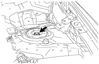
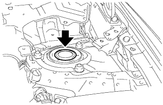
Fully tighten the front support to front shock absorber nut.
- Torque:
- 47 N*m { 479 kgf*cm, 35 ft.*lbf }
Note
Perform this step only when the front shock absorber with coil spring has been disassembled.
-
-
INSTALL FRONT FLEXIBLE HOSE
-
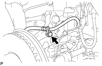
Install the front flexible hose to the steering knuckle with the bolt.
- Torque:
- 29 N*m { 296 kgf*cm, 21 ft.*lbf }
-
-
INSTALL FRONT SPEED SENSOR
-
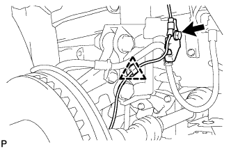
Install the front speed sensor and front flexible hose to the front shock absorber with the bolt and clamp.
- Torque:
- 29 N*m { 296 kgf*cm, 21 ft.*lbf }
Note
Do not twist the front speed sensor when installing it.
Tech Tips
Install the front front flexible hose first and then the speed sensor harness bracket.
-
-
INSTALL FRONT STABILIZER LINK ASSEMBLY
-
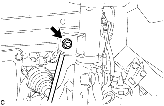
Install the front stabilizer link assembly to the front shock absorber with coil spring with the nut.
- Torque:
- 74 N*m { 755 kgf*cm, 55 ft.*lbf }
Tech Tips
If the ball joint turns together with the nut, use a hexagon wrench (6 mm) to hold the stud bolt.
-
-
INSTALL FRONT SUSPENSION SUPPORT DUST COVER
-
Install the front suspension support dust cover.
-
-
INSTALL FRONT WHEEL
- Torque:
- 103 N*m { 1050 kgf*cm, 76 ft.*lbf }
-
INSTALL OUTER COWL TOP PANEL (for LHD)
-
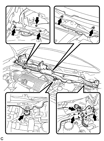
Install the outer cowl top panel with the 8 bolts and nut.
- Torque:
- Bolt
- 8.8 N*m { 90 kgf*cm, 78 in.*lbf }
- Nut
- 12 N*m { 122 kgf*cm, 9 ft.*lbf }
-
Engage the clamp.
-
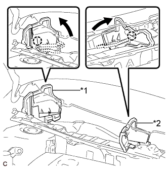
Text in Illustration *1 No. 1 Heater Air Duct Splash Shield Seal *2 Water Guard Plate RH Bend the No. 1 heater air duct splash shield seal and water guard plate RH, and engage each claw.
-
-
INSTALL OUTER COWL TOP PANEL (for RHD)
-
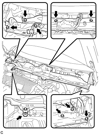
Install the outer cowl top panel with the 8 bolts and nut.
- Torque:
- Bolt
- 8.8 N*m { 90 kgf*cm, 78 in.*lbf }
- Nut
- 12 N*m { 122 kgf*cm, 9 ft.*lbf }
-
Engage the clamp of the wire harness.
-
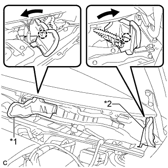
Text in Illustration *1 Water Guard Plate RH *2 No. 1 Heater Air Duct Splash Shield Seal Bend the water guard plate RH and No. 1 heater air duct splash shield seal, and engage each claw.
-
-
INSTALL COWL BODY MOUNTING REINFORCEMENT LH (for LHD)
-
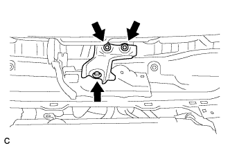
Install the cowl body mounting reinforcement LH with the 3 bolts.
- Torque:
- 8.8 N*m { 90 kgf*cm, 78 in.*lbf }
-
-
INSTALL COWL BODY MOUNTING REINFORCEMENT LH (for RHD)
-
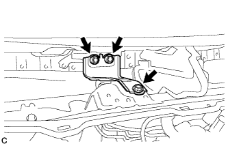
Install the cowl body mounting reinforcement LH with the 3 bolts.
- Torque:
- 8.8 N*m { 90 kgf*cm, 73 in.*lbf }
-
-
INSTALL WINDSHIELD WIPER MOTOR AND LINK ASSEMBLY
-
STABILIZE SUSPENSION
-
Lower the vehicle.
-
Press down on the vehicle several times to stabilize the suspension.
-
-
INSPECT AND ADJUST FRONT WHEEL ALIGNMENT