FRONT DRIVE SHAFT ASSEMBLY INSTALLATION
-
INSTALL FRONT DRIVE SHAFT HOLE SNAP RING
-
Install a new front drive shaft hole snap ring to the front drive inboard joint assembly.
Tech Tips
Face the end gap of the front drive inboard joint hole snap ring downward.
-
-
INSTALL FRONT DRIVE SHAFT ASSEMBLY LH
-
Coat the spline of the inboard joint shaft with transaxle fluid.
-
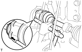
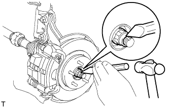
Align the shaft splines and tap in the drive shaft with a brass bar and a hammer.
Note
-
Face the end gap of the front drive shaft hole snap ring downward.
-
Do not damage the transaxle case oil seal.
-
Do not damage the inboard joint boot.
-
Make sure to center the front drive shaft assembly during installation to prevent damage to the front drive shaft hole snap ring.
-
-
-
INSTALL FRONT DRIVE SHAFT ASSEMBLY RH
Tech Tips
Perform the same procedure as for the LH side.
-
CONNECT FRONT AXLE ASSEMBLY LH
-
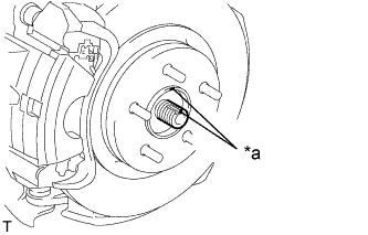
Text in Illustration *a Matchmark Align the matchmarks and connect the front drive shaft assembly to the front axle assembly LH.
-
-
CONNECT FRONT AXLE ASSEMBLY RH
Tech Tips
Perform the same procedure as for the LH side.
-
CONNECT FRONT NO. 1 LOWER SUSPENSION ARM SUB-ASSEMBLY LH
-
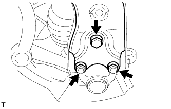
Connect the front No. 1 lower suspension arm sub-assembly to the front lower ball joint with the bolt and 2 nuts.
- Torque:
- 89 N*m { 908 kgf*cm, 66 ft.*lbf }
-
-
CONNECT FRONT NO. 1 LOWER SUSPENSION ARM SUB-ASSEMBLY RH
Tech Tips
Perform the same procedure as for the LH side.
-
INSTALL FRONT STABILIZER LINK ASSEMBLY LH
-
Install the front stabilizer link assembly to the front shock absorber with coil spring with the nut.
- Torque:
- 74 N*m { 755 kgf*cm, 55 ft.*lbf }
Tech Tips
If the ball joint turns together with the nut, use a hexagon wrench (6 mm) to hold the stud bolt.
-
-
INSTALL FRONT STABILIZER LINK ASSEMBLY RH
Tech Tips
Perform the same procedure as for the LH side.
-
INSTALL FRONT FLEXIBLE HOSE LH
-
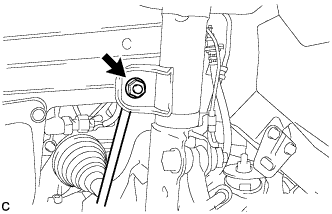
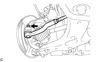
Install the front flexible hose to the steering knuckle with the bolt.
- Torque:
- 29 N*m { 296 kgf*cm, 21 ft.*lbf }
-
-
INSTALL FRONT FLEXIBLE HOSE RH
Tech Tips
Perform the same procedure as for the LH side.
-
INSTALL FRONT SPEED SENSOR LH
-
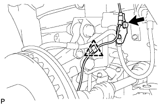
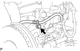
Install the front speed sensor and front flexible hose to the front shock absorber with the bolt and clamp.
- Torque:
- 29 N*m { 296 kgf*cm, 21 ft.*lbf }
Note
Do not twist the front speed sensor when installing it.
Tech Tips
Install the front flexible hose first and then the speed sensor harness bracket.
-
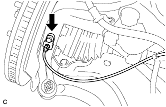
Install the front speed sensor to the steering knuckle with the bolt.
- Torque:
- 8.5 N*m { 87 kgf*cm, 75 in.*lbf }
Note
Do not twist the front speed sensor when installing it.
-
-
INSTALL FRONT SPEED SENSOR RH
Tech Tips
Perform the same procedure as for the LH side.
-
CONNECT TIE ROD END SUB-ASSEMBLY LH
-
Connect the tie rod end sub-assembly LH to the steering knuckle with the nut.
- Torque:
- 49 N*m { 500 kgf*cm, 36 ft.*lbf }
Note
Further tighten the nut up to 60° if the holes for the cotter pin are not aligned.
-
Install a new cotter pin.
-
-
CONNECT TIE ROD END SUB-ASSEMBLY RH
Tech Tips
Perform the same procedure as for the LH side.
-
INSTALL FRONT AXLE SHAFT NUT LH
-
Clean the threaded parts on the drive shaft and axle shaft nut using a non-residue solvent.
Note
-
Be sure to perform this work for a new drive shaft.
-
Keep the threaded parts free of oil and foreign objects.
-
-
Using a socket wrench (30 mm), install a new axle shaft nut.
- Torque:
- 216 N*m { 2203 kgf*cm, 159 ft.*lbf }
-
Using a chisel and hammer, stake the front axle shaft nut.
-
-
INSTALL FRONT AXLE SHAFT NUT RH
Tech Tips
Perform the same procedure as for the LH side.
-
ADD HYBRID TRANSAXLE FLUID
-
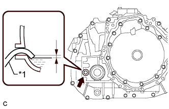
Text in Illustration *1 Filler nozzle Add transaxle fluid until the fluid level is between 0 to 10 mm (0 to 0.394 in.) from the bottom lip of the filler plug opening.
Note
-
Stop the vehicle on a level surface.
-
Recheck the transaxle fluid level after driving following fluid replacement.
-
Insufficient or excessive amounts of transaxle fluid may damage the hybrid transaxle.
-
Be sure to add fluid slowly. If fluid is added quickly, the fluid may hit internal parts and bounce back, resulting in fluid coming out of the filler plug opening.
-
Be sure to fully insert the filler nozzle into the filler plug opening.
Reference 3.4 liters (3.6 US qts, 3.0 lmp.qts) Fluid Type Toyota Genuine ATF WS -
-
-
INSPECT HYBRID TRANSAXLE FLUID
-
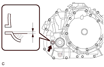
After adding fluid, leave it for 30 seconds so that the fluid surface can become still again, and then check that the fluid level is between 0 to 10 mm (0 to 0.394 in.) from the bottom lip of the filler plug opening. (If the fluid is insufficient, return to the Add Hybrid Transaxle Fluid procedure.)
Note
-
Stop the vehicle on a level surface.
-
Recheck the transaxle fluid level after driving following fluid replacement.
-
Insufficient or excessive amounts of transaxle fluid may damage the hybrid transaxle.
-
Be sure to add fluid slowly. If fluid is added quickly, the fluid may hit internal parts and bounce back, resulting in fluid coming out of the filler plug opening.
-
Be sure to directly check that the transaxle fluid level is within the specified range.
-
-
Check for leaks if the quantity of transaxle fluid is low.
-
Using a 10 mm hexagon socket wrench, install the filler plug with a new gasket.
- Torque:
- 50 N*m { 510 kgf*cm, 37 ft.*lbf }
-
-
INSPECT FOR TRANSAXLE FLUID LEAK
-
INSTALL FRONT WHEEL
- Torque:
- 103 N*m { 1050 kgf*cm, 76 ft.*lbf }
-
INSPECT AND ADJUST FRONT WHEEL ALIGNMENT
-
CHECK SPEED SENSOR SIGNAL
-
INSTALL REAR ENGINE UNDER COVER LH
-
INSTALL REAR ENGINE UNDER COVER RH
-
INSTALL NO.1 ENGINE UNDER COVER