HYBRID VEHICLE TRANSAXLE UNIT REASSEMBLY

-
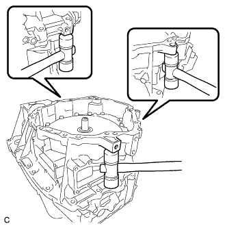
INSTALL STRAIGHT PIN
-
Install the 2 straight pins to the hybrid vehicle motor assembly.
Standard protrusion 7.0 to 8.5 mm (0.276 to 0.335 in.)
-
-
INSTALL RADIAL BALL BEARING (LH SIDE)
-
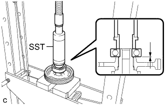
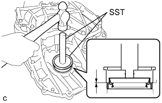
Using SST and a press, install the radial ball bearing (LH side) to the counter driven gear sub-assembly.
- SST
- 09316-60011 ( 09316-00011, 09316-00071 )
Note
Be sure to install the radial ball bearing (LH side) so that there is no clearance between the radial ball bearing (LH side) and the counter driven gear sub-assembly.
-
-
INSTALL RADIAL BALL BEARING (RH SIDE)
-
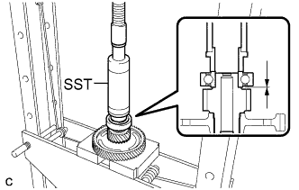
Using SST and a press, install the radial ball bearing (RH side) to the counter driven gear sub-assembly.
- SST
- 09316-60011 ( 09316-00011, 09316-00071 )
Note
Be sure to install the radial ball bearing (RH side) so that there is no clearance between the radial ball bearing (RH side) and the differential drive pinion.
-
-
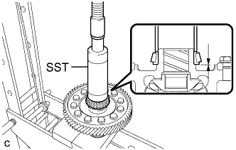
INSTALL TAPERED ROLLER BEARING (RH SIDE INNER RACE)
-
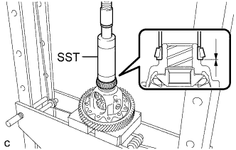
Using SST and a press, install the tapered roller bearing (RH side inner race) to the differential case sub-assembly.
- SST
- 09316-60011 ( 09316-00011 )
Note
Be sure to install the tapered roller bearing (RH side inner race) so that there is no clearance between the tapered roller bearing (RH side inner race) and the differential case sub-assembly.
-
-
INSTALL TAPERED ROLLER BEARING (LH SIDE INNER RACE)
-
Using SST and a press, install the tapered roller bearing (LH side inner race) to the differential case sub-assembly.
- SST
- 09316-60011 ( 09316-00011 )
Note
Be sure to install the tapered roller bearing (LH side inner race) so that there is no clearance between the tapered roller bearing (LH side inner race) and the differential case sub-assembly.
-
-
INSTALL TAPERED ROLLER BEARING (LH SIDE OUTER RACE)
-
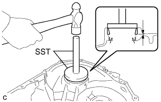
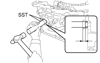
Using SST and hammer, install the tapered roller bearing (LH side outer race) to the hybrid vehicle motor assembly.
- SST
- 09950-60020 ( 09951-00750 )
- 09950-70010 ( 09951-07200 )
Note
-
If the tapered roller bearing (LH side outer race) is deformed or damaged, replace it with a new one.
-
Be sure to install the tapered roller bearing (LH side outer race) so that there is no clearance between the tapered roller bearing (LH side outer race) and the hybrid vehicle motor assembly.
-
-
INSTALL TAPERED ROLLER BEARING (RH SIDE OUTER RACE)
-
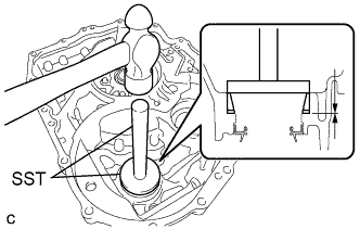
Using SST and hammer, install the tapered roller bearing (RH side outer race) and differential case RH shim to the hybrid vehicle generator assembly.
- SST
- 09950-60020 ( 09951-00750 )
- 09950-70010 ( 09951-07200 )
Note
-
If the differential case RH shim or tapered roller bearing (RH side outer race) is deformed or damaged, replace it with a new one.
-
Be sure to install the tapered roller bearing (RH side outer race) so that there is no clearance between the tapered roller bearing (RH side outer race) and the hybrid vehicle generator assembly.
-
-
ADJUST PRELOAD
-
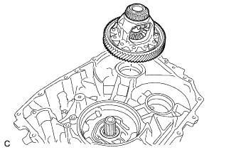
Install the differential case sub-assembly to the hybrid vehicle motor assembly.
-
Install the No. 1 engine hanger and No. 2 engine hanger with the 2 bolts and washer as shown in the illustration.
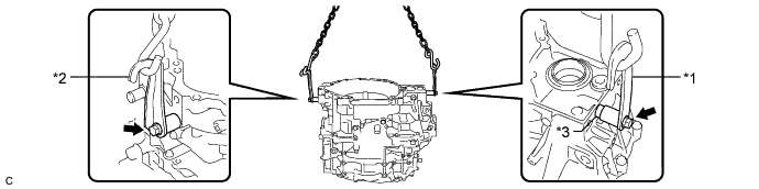
Text in Illustration *1 No. 1 Engine Hanger *2 No. 2 Engine Hanger *3 Washer - - - Torque:
- 43 N*m { 438 kgf*cm, 32 ft.*lbf }
Part Name Part No. No. 1 engine hanger 12281-37050 No. 2 engine hanger 12282-37040 Bolt 91552-81050 Tech Tips
When installing the No. 1 engine hanger, use a washer with an appropriate thickness so that the No. 1 engine hanger will not interfere with the installation surface of the transaxle housing.
-
Using the sling device and chain block, install the hybrid vehicle generator assembly to the hybrid vehicle motor assembly.
-
Install the 8 bolts to the hybrid vehicle generator assembly.
- Torque:
- 29 N*m { 300 kgf*cm, 22 ft.*lbf }
-
Install the 2 bolts to the hybrid vehicle motor assembly.
- Torque:
- 29 N*m { 300 kgf*cm, 22 ft.*lbf }
-
Install the 8 bolts to the hybrid vehicle generator assembly.
- Torque:
- 29 N*m { 300 kgf*cm, 22 ft.*lbf }
-
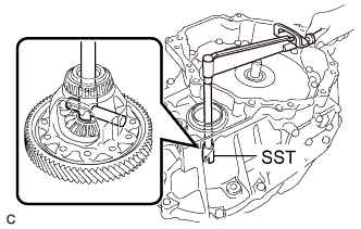
Using SST and a torque wrench, measure the starting torque of the differential case sub-assembly.
- SST
- 09564-33010
Standard preload Starting Torque New tapered roller bearing 1.3 to 2.9 N*m (13 to 30 kgf*cm, 12 to 26 in.*lbf) Reused tapered roller bearing 0.9 to 1.3 N*m (9 to 13 kgf*cm, 8 to 12 in.*lbf) Note
-
Before measurement, turn the differential pinion shaft in both directions to settle the bearings.
-
If the differential case RH shim or tapered roller bearing (RH side outer race) is deformed or damaged, replace it with a new one.
Tech Tips
If the value is not as specified, replace the differential case RH shim with one of the correct thickness.
Differential Case RH Shim Thickness Part No. Thickness (mm (in.)) Part No. Thickness (mm (in.)) 90564-64031 1.70 (0.0669) 90564-64039 2.10 (0.0827) 90564-64047 1.725 (0.0679) 90564-64055 2.125 (0.0837) 90564-64032 1.75 (0.0689) 90564-64040 2.15 (0.0846) 90564-64048 1.775 (0.0699) 90564-64056 2.175 (0.0856) 90564-64033 1.80 (0.0709) 90564-64041 2.20 (0.0866) 90564-64049 1.825 (0.0719) 90564-64057 2.225 (0.0876) 90564-64034 1.85 (0.0728) 90564-64042 2.25 (0.0886) 90564-64050 1.875 (0.0738) 90564-64058 2.275 (0.0896) 90564-64035 1.90 (0.0748) 90564-64043 2.30 (0.0906) 90564-64051 1.925 (0.0758) 90564-64059 2.325 (0.0915) 90564-64036 1.95 (0.0768) 90564-64044 2.35 (0.0925) 90564-64052 1.975 (0.0778) 90564-64060 2.375 (0.0935) 90564-64037 2.00 (0.0787) 90564-64045 2.40 (0.0945) 90564-64053 2.025 (0.0797) 90564-64061 2.425 (0.0955) 90564-64038 2.05 (0.0807) 90564-64046 2.45 (0.0965) 90564-64054 2.075 (0.0817) - - -
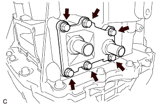
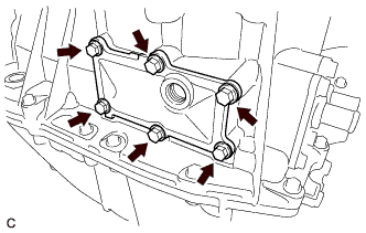
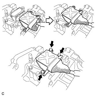
Remove the 18 bolts from the hybrid vehicle motor assembly and hybrid vehicle generator assembly.
-
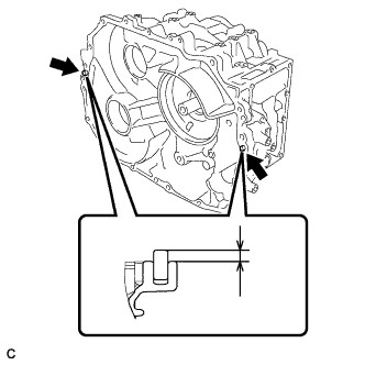
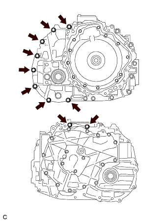
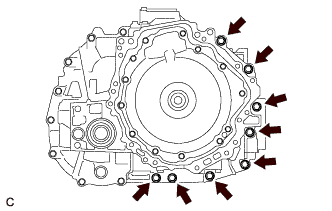
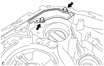
While lifting the hybrid vehicle generator assembly with a chain, tap the areas shown in the illustration with a plastic hammer and separate the hybrid vehicle generator assembly from the hybrid vehicle motor assembly.
-
While lifting the hybrid vehicle generator assembly with a chain, remove it from the hybrid vehicle motor assembly.
Note
Lift the hybrid vehicle generator assembly straight up.
-
Remove the differential case sub-assembly from the hybrid vehicle motor assembly.
-
Remove the 2 bolts, washer, No. 1 engine hanger and No. 2 engine hanger from the hybrid vehicle generator assembly.
-
-
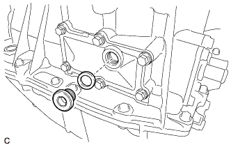
INSTALL SHIFT CONTROL ACTUATOR SEAL
-
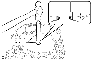
Using SST and hammer, install a new shift control actuator seal to the hybrid vehicle motor assembly.
- SST
- 09950-60010 ( 09951-00210 )
- 09950-70010 ( 09951-07100 )
Standard depth 8.5 to 9.8 mm (0.335 to 0.386 in.) -
Coat the lip of the shift control actuator seal with a small amount of MP grease.
-
-
INSTALL HYBRID VEHICLE TRANSAXLE ASSEMBLY TYPE T OIL SEAL (LH SIDE)
-
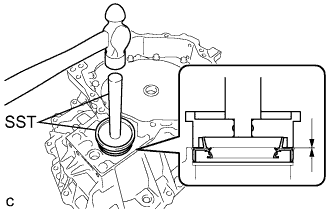
Using SST and hammer, install a new hybrid vehicle transaxle assembly type T oil seal (LH side) to the hybrid vehicle motor assembly.
- SST
- 09608-32010
- 09950-70010 ( 09951-07150 )
Standard depth -0.5 to 0.5 mm (-0.0197 to 0.0197 in.) Note
-
Do not allow foreign matter to attach to the hybrid vehicle transaxle assembly type T oil seal (LH side) lip.
-
Do not install the hybrid vehicle transaxle assembly type T oil seal (LH side) at an angle.
-
Coat the lip of the hybrid vehicle transaxle assembly type T oil seal (LH side) with a small amount of MP grease.
-
-
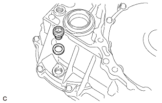
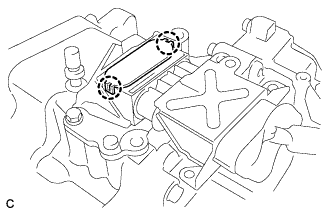
INSTALL TRANSMISSION OIL STRAINER
-
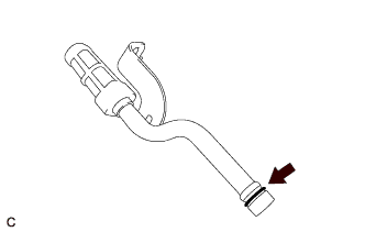
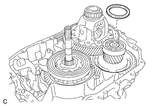
Coat a new O-ring with ATF and install them to the transmission oil strainer.
-
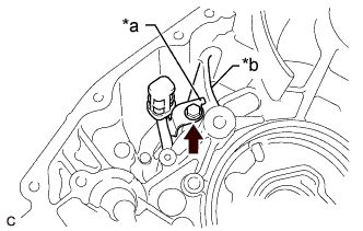
Text in Illustration *a Detent *b Rib Install the transmission oil strainer to the hybrid vehicle motor assembly with the bolt.
- Torque:
- 15 N*m { 153 kgf*cm, 11 ft.*lbf }
Note
Place the detent of the transmission oil strainer to the rib.
-
-
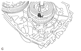
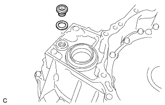
INSTALL REAR PLANETARY SUN GEAR
-
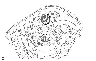
Install the rear planetary sun gear to the hybrid vehicle motor assembly.
-
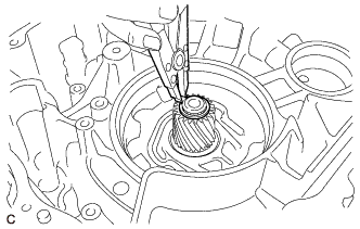
Using a snap ring expander, install a new rear planetary sun gear snap ring to the hybrid vehicle motor assembly.
Note
Do not expand the rear planetary sun gear shaft snap ring excessively.
Tech Tips
Turn the transaxle case sideways, pull out the rotor shaft, and install the rear planetary sun gear shaft snap ring.
-
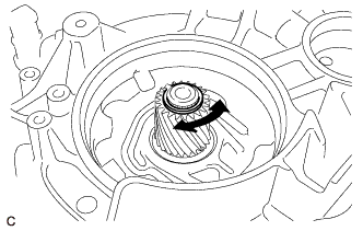
Turn the rear planetary sun gear shaft snap ring and check that it is not loose.
-
-
INSTALL NO. 1 REAR PLANETARY GEAR ASSEMBLY
-
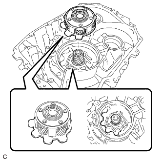
Install the No. 1 rear planetary gear assembly to the rear planetary sun gear.
-
-
INSTALL COUNTER DRIVE GEAR SUB-ASSEMBLY
-
Install the counter drive gear sub-assembly to the No. 1 rear planetary gear assembly.
-
-
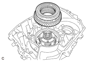
INSTALL COUNTER DRIVEN GEAR SUB-ASSEMBLY
-
Install the counter driven gear sub-assembly to the hybrid vehicle motor assembly.
-
-
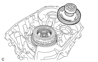
INSTALL DIFFERENTIAL CASE SUB-ASSEMBLY
-
Install the differential case sub-assembly to the hybrid vehicle motor assembly.
-
-
INSTALL THRUST NEEDLE ROLLER BEARING
-
Apply ATF to the contact surfaces of the thrust needle roller bearing.
-
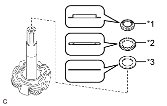
Text in Illustration *1 Thrust Bearing Race *2 Thrust Needle Roller Bearing *3 No. 1 Thrust Bearing Race Install the No. 1 thrust bearing race, thrust needle roller bearing and thrust bearing race to the input shaft assembly.
-
-
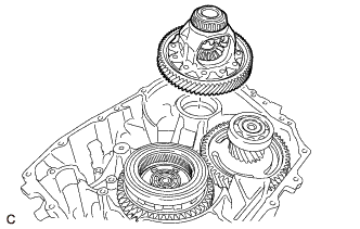
INSTALL INPUT SHAFT ASSEMBLY
-
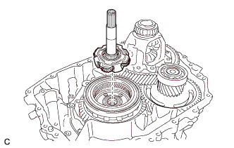
Install the input shaft assembly to the counter drive gear sub-assembly.
-
-
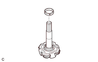
INSTALL PLANETARY SUN GEAR
-
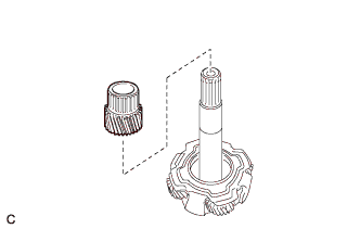
Install the planetary sun gear to the input shaft assembly.
-
Select a planetary sun gear snap ring.
-
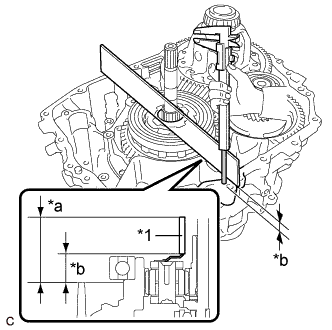
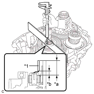
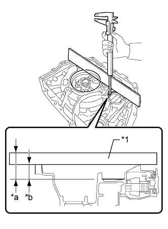
Text in Illustration *1 Straightedge *a Measured area *b Dimension A Using a straightedge and vernier caliper, measure dimension A shown in the illustration.
Dimension A Measured value - Straightedge thickness -
Text in Illustration *1 Straightedge *a Measured area *b Dimension B Using a straightedge and vernier caliper, measure dimension B shown in the illustration.
Dimension B Measured value - Straightedge thickness Note
Measure the dimensions without a planetary sun gear snap ring installed.
-
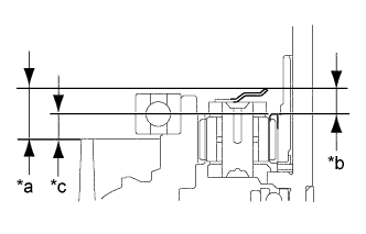
Text in Illustration *a Dimension A *b Dimension B *c Dimension C Measure the dimension C.
Dimension C Dimension A - Dimension B -
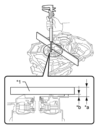
Text in Illustration *1 Straightedge *a Measured area *b Dimension D Using a straightedge and vernier caliper, measure dimension D shown in the illustration.
Dimension D Measured value - Straightedge thickness -
Select a planetary sun gear snap ring.
Standard value Planetary sun gear snap ring thickness = (Dimension D - Dimension C) - (0.1 to 0.2 mm (0.00394 to 0.00787 in.)) Note
There should be a clearance of 0.1 to 0.2 mm (0.00394 to 0.00787 in.) for the input shaft assembly. Therefore, use the above formula when selecting a planetary sun gear snap ring.
Planetary Sun Gear Snap Ring Thickness Part No. Thickness (mm (in.)) Part No. Thickness (mm (in.)) 90520-31035 3.88 (0.153) 90520-31050 4.33 (0.170) 90520-31036 3.91 (0.154) 90520-31051 4.36 (0.172) 90520-31037 3.94 (0.155) 90520-31052 4.39 (0.173) 90520-31038 3.97 (0.156) 90520-31053 4.42 (0.174) 90520-31039 4.00 (0.157) 90520-31054 4.45 (0.175) 90520-31040 4.03 (0.159) 90520-31055 4.48 (0.176) 90520-31041 4.06 (0.160) 90520-31056 4.51 (0.178) 90520-31042 4.09 (0.161) 90520-31057 4.54 (0.179) 90520-31043 4.12 (0.162) 90520-31058 4.57 (0.180) 90520-31044 4.15 (0.163) 90520-31059 4.60 (0.181) 90520-31045 4.18 (0.165) 90520-31060 4.63 (0.182) 90520-31046 4.21 (0.166) 90520-31061 4.66 (0.183) 90520-31047 4.24 (0.167) 90520-31062 4.69 (0.185) 90520-31048 4.27 (0.168) 90520-31063 4.72 (0.186) 90520-31049 4.30 (0.169) - -
-
-
Install the planetary sun gear snap ring to the input shaft assembly.
-
-
INSTALL COUNTER DRIVEN GEAR SHIM
-
Select a counter driven gear shim.
-
Text in Illustration *1 Straightedge *a Measured area *b Dimension A Using a straightedge and vernier caliper, measure dimension A shown in the illustration.
Dimension A Measured value - Straightedge thickness -
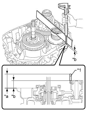
Text in Illustration *1 Straightedge *a Measured area *b Dimension B Using a straightedge and vernier caliper, measure dimension B shown in the illustration.
Dimension B Measured value - Straightedge thickness -
Select a counter driven gear shim.
Standard value Counter driven gear shim thickness = (Dimension A - Dimension B) - (0 to 0.2 mm (0 to 0.00787 in.)) Note
There should be a clearance of 0 to 0.2 mm (0 to 0.00787 in.) for the counter driven gear sub-assembly. Therefore, use the above formula when selecting a counter driven gear shim.
Counter Driven Gear Shim Thickness Part No. Thickness (mm (in.)) Part No. Thickness (mm (in.)) 90564-50281 2.00 (0.0787) 90564-50288 2.35 (0.0925) 90564-50282 2.05 (0.0807) 90564-50289 2.40 (0.0945) 90564-50283 2.10 (0.0827) 90564-50290 2.45 (0.0965) 90564-50284 2.15 (0.0846) 90564-50291 2.50 (0.0984) 90564-50285 2.20 (0.0866) 90564-50292 2.55 (0.100) 90564-50286 2.25 (0.0886) 90564-50293 2.60 (0.102) 90564-50287 2.30 (0.0906) - -
-
-
Install the counter driven gear shim to the counter driven gear sub-assembly.
-
-
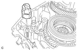
INSTALL NO. 1 TRANSMISSION MAGNET
-
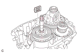
Install the No. 1 transmission magnet to the hybrid vehicle motor assembly.
-
-
INSTALL PARKING LOCK ROD SUB-ASSEMBLY
-
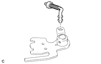
Align the slot with the notches on the No. 1 parking lock lever sub-assembly and install the parking lock rod sub-assembly.
-
-
INSTALL NO. 1 PARKING LOCK SHAFT
-
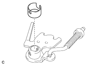
Install a new spacer to the No. 1 parking lock lever sub-assembly.
-
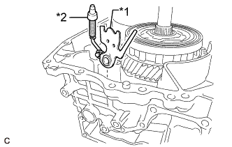
Text in Illustration *1 No. 1 Parking Lock Lever Sub-assembly *2 Parking Lock Rod Sub-assembly Install the No. 1 parking lock lever sub-assembly and parking lock rod sub-assembly to the hybrid vehicle motor assembly.
-
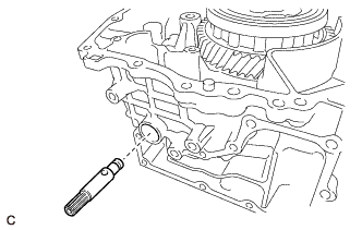
Install the No. 1 parking lock shaft to the hybrid vehicle motor assembly.
-
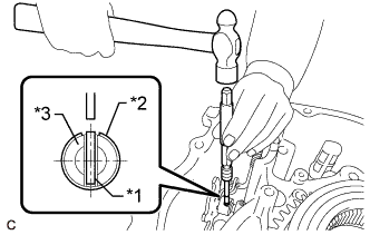
Text in Illustration *1 Slotted Spring Pin *2 Spacer *3 No. 1 Parking Lock Shaft Using a 5 mm pin punch and hammer, drive in a new slotted spring pin to the No. 1 parking lock shaft.
-
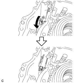
Turn the spacer as shown in the illustration.
-
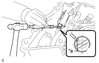
Text in Illustration *a Stake point Using a 3 mm pin punch and hammer, stake the spacer.
Note
After staking the spacer, make sure that it is firmly secured.
-
-
INSTALL RETAINER SPRING
-
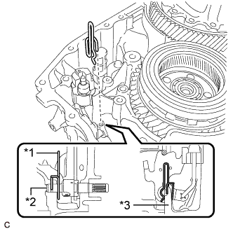
Text in Illustration *1 Retainer Spring *2 No. 1 Parking Lock Shaft *3 Hybrid Vehicle Motor Assembly Install the retainer spring to the hybrid vehicle motor assembly and No. 1 parking lock shaft.
-
-
INSTALL MANUAL DETENT SPRING SUB-ASSEMBLY
-
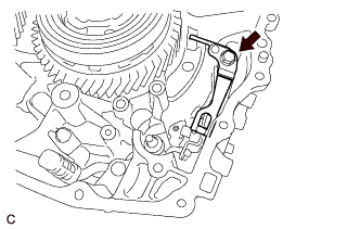
Install the manual detent spring sub-assembly to the hybrid vehicle motor assembly with the bolt.
- Torque:
- 25 N*m { 250 kgf*cm, 18 ft.*lbf }
-
-
INSTALL PARKING LOCK SLEEVE
-
Install the parking lock sleeve to the hybrid vehicle motor assembly.
-
-
INSTALL TORSION SPRING
-
Install the parking lock pawl shaft and torsion spring to the hybrid vehicle motor assembly.
-
-
INSTALL PAWL STOPPER PLATE
-
Install the pawl stopper plate to the hybrid vehicle motor assembly with the 2 bolts.
- Torque:
- 25 N*m { 250 kgf*cm, 18 ft.*lbf }
-
-
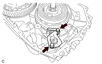
INSTALL PARKING LOCK PAWL
-
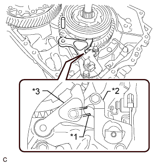
Text in Illustration *1 Torsion Spring *2 Pawl Stopper Plate *3 Parking Lock Pawl Install the parking lock pawl to the hybrid vehicle motor assembly with the parking lock pawl shaft.
Note
Make sure the torsion spring is attached to the parking lock pawl and pawl stopper plate.
-
-
INSTALL INPUT SHAFT TYPE T OIL SEAL
-
Using SST and hammer, install a new input shaft type T oil seal to the hybrid vehicle generator assembly.
- SST
- 09950-60010 ( 09951-00340 )
- 09950-70010 ( 09951-07150 )
Standard depth 1.0 to 1.8 mm (0.0394 to 0.0709 in.) Note
-
Do not allow foreign matter to attach to the input shaft type T oil seal lip.
-
Do not install the input shaft type T oil seal at an angle.
-
Coat the lip of the input shaft type T oil seal with a small amount of MP grease.
-
-
INSTALL HYBRID VEHICLE TRANSAXLE ASSEMBLY TYPE T OIL SEAL (RH SIDE)
-
Using SST and hammer, install a new hybrid vehicle transaxle assembly type T oil seal (RH side) to the hybrid vehicle generator assembly.
- SST
- 09608-10010
- 09950-70010 ( 09951-07150 )
Standard depth -0.5 to 0.5 mm (-0.0197 to 0.0197 in.) Note
-
Do not allow foreign matter to attach to the hybrid vehicle transaxle assembly type T oil seal (RH side) lip.
-
Do not install the hybrid vehicle transaxle assembly type T oil seal (RH side) at an angle.
-
Coat the lip of the hybrid vehicle transaxle assembly type T oil seal (RH side) with a small amount of MP grease.
-
-
INSTALL TRANSAXLE HOUSING OIL SEPARATOR
-
Install the transaxle housing oil separator to the hybrid vehicle generator assembly with the 2 bolts.
- Torque:
- 15 N*m { 153 kgf*cm, 11 ft.*lbf }
-
-
INSTALL HYBRID VEHICLE GENERATOR ASSEMBLY
-
Clean the hybrid vehicle motor assembly installation surface of the hybrid vehicle generator assembly.
Note
-
Do not allow any remaining seal packing to enter the hybrid vehicle generator assembly.
-
Do not damage the installation surface.
-
-
Clean the hybrid vehicle generator assembly installation surface of the hybrid vehicle motor assembly.
Note
-
Do not allow any remaining seal packing to enter the hybrid vehicle motor assembly.
-
Do not damage the installation surface.
-
-
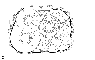
Apply seal packing to the hybrid vehicle motor assembly as shown in the illustration.
Text in Illustration 
Seal Packing Seal packing Toyota Genuine Seal Packing 1281, Three Bond 1281 or equivalent Standard seal diameter 1.5 mm (0.0591 in.) Note
-
Clean the installation surfaces.
-
Check and clean the bolts and bolt holes.
-
Install the hybrid vehicle generator assembly within 3 minutes and tighten the bolts within 10 minutes of applying the seal packing.
-
Make sure to overlap the start and the end points of the seal packing.
-
Do not add fluid for at least 2 hours after installing the hybrid vehicle generator assembly.
-
Do not start the engine for at least 2 hours after installing the hybrid vehicle generator assembly.
-
-
Install the No. 1 engine hanger and No. 2 engine hanger with the 2 bolts and washer as shown in the illustration.
Text in Illustration *1 No. 1 Engine Hanger *2 No. 2 Engine Hanger *3 Washer - - - Torque:
- 43 N*m { 438 kgf*cm, 32 ft.*lbf }
Part Name Part No. No. 1 engine hanger 12281-37050 No. 2 engine hanger 12282-37040 Bolt 91552-81050 Tech Tips
When installing the No. 1 engine hanger, use a washer with an appropriate thickness so that the No. 1 engine hanger will not interfere with the installation surface of the transaxle housing.
-
Using the sling device and chain block, install the hybrid vehicle generator assembly to the hybrid vehicle motor assembly.
Note
-
Lift the hybrid vehicle generator assembly straight up.
-
Do not damage the input shaft type T oil seal with the input shaft assembly.
-
If it is difficult to install the hybrid vehicle generator assembly, turn the input shaft assembly left and right and engage the gears.
-
Do not directly hold the splines of the input shaft assembly with a tool when turning it.
-
-
Remove the 2 bolts, washer, No. 1 engine hanger and No. 2 engine hanger from the hybrid vehicle generator assembly.
-
Install the 8 bolts to the hybrid vehicle generator assembly.
- Torque:
- 29 N*m { 300 kgf*cm, 22 ft.*lbf }
-
Install the 2 bolts to the hybrid vehicle motor assembly.
- Torque:
- 29 N*m { 300 kgf*cm, 22 ft.*lbf }
-
Install the 8 bolts to the hybrid vehicle generator assembly.
- Torque:
- 29 N*m { 300 kgf*cm, 22 ft.*lbf }
-
-
INSTALL NO. 2 MOTOR WATER JACKET COVER ASSEMBLY
-
Clean the No. 2 motor water jacket cover assembly installation surface of the hybrid vehicle transaxle assembly.
Note
Do not allow any remaining seal packing to enter the coolant path.
-
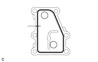
Apply seal packing to the No. 2 motor water jacket cover assembly as shown in the illustration.
Text in Illustration Seal Packing Seal packing Toyota Genuine Seal Packing 1282B, Three Bond 1282B or equivalent Standard seal diameter 1.5 mm (0.0591 in.) Note
-
Clean and degrease the installation surface.
-
Clean and degrease the bolt and bolt holes.
-
Install the No. 2 motor water jacket cover assembly within 3 minutes and tighten the bolts within 10 minutes of applying the seal packing.
-
Make sure to overlap the start and the end points of the seal packing.
-
Do not add coolant for at least 2 hours after installing the No. 2 motor water jacket cover assembly.
-
Do not power switch on (READY) for at least 2 hours after installing the No. 2 motor water jacket cover assembly.
-
-
Install the No. 2 motor water jacket cover assembly to the hybrid vehicle transaxle assembly with the 6 bolts.
- Torque:
- 18 N*m { 184 kgf*cm, 13 ft.*lbf }
-
-
INSTALL NO. 1 MOTOR WATER JACKET COVER ASSEMBLY
-
Clean the No. 1 motor water jacket cover assembly installation surface of the hybrid vehicle transaxle assembly.
Note
Do not allow any remaining seal packing to enter the coolant path.
-
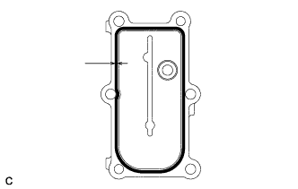
Apply seal packing to the No. 1 motor water jacket cover assembly as shown in the illustration.
Text in Illustration Seal Packing Seal packing Toyota Genuine Seal Packing 1282B, Three Bond 1282B or equivalent Standard seal diameter 1.5 mm (0.0591 in.) Note
-
Clean and degrease the installation surface.
-
Clean and degrease the bolt and bolt holes.
-
Install the No. 1 motor water jacket cover assembly within 3 minutes and tighten the bolts within 10 minutes of applying the seal packing.
-
Make sure to overlap the start and the end points of the seal packing.
-
Do not add coolant for at least 2 hours after installing the No. 1 motor water jacket cover assembly.
-
Do not power switch on (READY) for at least 2 hours after installing the No. 1 motor water jacket cover assembly.
-
-
Install the No. 1 motor water jacket cover assembly to the hybrid vehicle transaxle assembly with the 6 bolts.
- Torque:
- 18 N*m { 184 kgf*cm, 13 ft.*lbf }
-
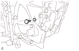
Using a 10 mm hexagon socket wrench, install the drain plug and a new gasket to the No. 1 motor water jacket cover assembly.
- Torque:
- 39 N*m { 400 kgf*cm, 29 ft.*lbf }
-
-
INSTALL DRAIN PLUG
-
Using a 10 mm hexagon socket wrench, install the drain plug and a new gasket to the hybrid vehicle transaxle assembly.
- Torque:
- 50 N*m { 510 kgf*cm, 37 ft.*lbf }
-
-
INSTALL FILLER PLUG
-
Using a 10 mm hexagon socket wrench, install the filler plug and a new gasket to the hybrid vehicle transaxle assembly.
- Torque:
- 50 N*m { 510 kgf*cm, 37 ft.*lbf }
-
-
INSTALL OIL PUMP DRIVE SHAFT
-
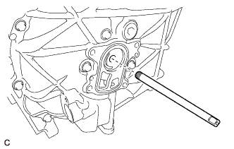
Install the oil pump drive shaft to the hybrid vehicle transaxle assembly.
-
-
INSTALL TRANSMISSION OIL PUMP COVER SUB-ASSEMBLY
-
Coat a new O-ring with ATF and install them to the hybrid vehicle transaxle assembly.
Note
Be careful not to damage the O-ring.
-
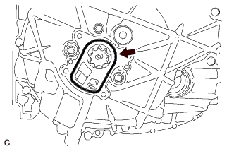
Apply ATF to the transaxle oil pump drive rotor and transmission oil pump driven rotor.
-
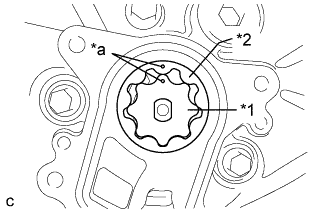
Text in Illustration *1 Transaxle Oil Pump Drive Rotor *2 Transmission Oil Pump Driven Rotor *a Matchmark Install the transaxle oil pump drive rotor and transmission oil pump driven rotor to the hybrid vehicle transaxle assembly.
Note
Align the matchmarks on the transmission oil pump drive rotor and the transmission oil pump driven rotor.
-
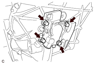
Install the transmission oil pump cover sub-assembly to the hybrid vehicle transaxle assembly with the 4 bolts.
- Torque:
- 11 N*m { 112 kgf*cm, 8 ft.*lbf }
Note
Do not pinch the O-ring.
-
Apply ATF to a new O-ring with ATF and install them to the fluid pump cover plug.
-
Install the fluid pump cover plug to the transmission oil pump cover sub-assembly.
- Torque:
- 8.0 N*m { 82 kgf*cm, 71 in.*lbf }
-
-
INSTALL WITH HEAD STRAIGHT SCREW PLUG
-
Clean and degrease the bolt holes.
-
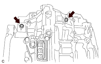
Using a 6 mm hexagon socket wrench, install 2 new with head straight screw plugs to the hybrid vehicle transaxle assembly.
- Torque:
- 18 N*m { 180 kgf*cm, 13 ft.*lbf }
-
-
INSTALL TRANSAXLE BREATHER PLUG
-
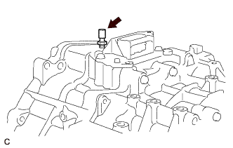
Using a union nut wrench, install the transaxle breather plug to the hybrid vehicle transaxle assembly.
- Torque:
- 11 N*m { 115 kgf*cm, 8 ft.*lbf }
Note
Be careful not to damage the transaxle breather plug.
-
-
INSTALL SHIFT CONTROL ACTUATOR ASSEMBLY
-
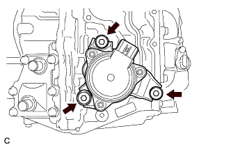
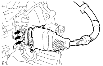
Install the shift control actuator assembly to the hybrid vehicle transaxle assembly with 3 new shift control actuator bolts.
- Torque:
- 9.5 N*m { 97 kgf*cm, 84 in.*lbf }
Tech Tips
-
Do not tap the shift control actuator assembly with a plastic hammer or similar tool when installing it.
-
As the position of the shift control actuator assembly is detected automatically, initialization is not necessary after disconnecting and reconnecting the cable to the auxiliary battery negative (-) terminal.
-

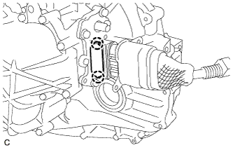
Install 3 new shift control actuator bolt caps to the shift control actuator bolts.
Note
Push in each shift control actuator bolt cap firmly until the claw of the shift control actuator bolt cap engages with the shift control actuator bolt.
-
-
INSTALL MOTOR CABLE
-
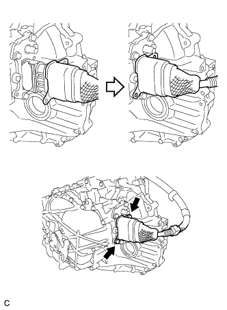
Install the motor cable to the hybrid vehicle transaxle assembly with the 3 bolts.
- Torque:
- 10 N*m { 102 kgf*cm, 7 ft.*lbf }
Note
-
Keep foreign matter, water, etc. away from the generator cable terminals and their installation area.
-
Insert the terminals straight in when installing the generator cable.
-
Engage the 2 claws to install a new terminal cap to the hybrid vehicle transaxle assembly.
Note
-
Keep foreign matter, water, etc. away from the terminal cap and its installation area.
-
Do not pinch the O-ring.
-
Check that the terminal cap is securely installed.
-
-
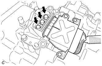
Place the motor cable connector shell in position and install it with the 3 bolts.
- Torque:
- 10 N*m { 102 kgf*cm, 7 ft.*lbf }
-
-
INSTALL GENERATOR CABLE
-
Install the generator cable to the hybrid vehicle transaxle assembly with the 3 bolts.
- Torque:
- 10 N*m { 102 kgf*cm, 7 ft.*lbf }
Note
-
Keep foreign matter, water, etc. away from the generator cable terminals and their installation area.
-
Insert the terminals straight in when installing the generator cable.
-
Engage the 2 claws to install a new terminal cap to the hybrid vehicle transaxle assembly.
Note
-
Keep foreign matter, water, etc. away from the terminal cap and its installation area.
-
Do not pinch the O-ring.
-
Check that the terminal cap is securely installed.
-
-
Place the generator cable connector shell in position and install it with the 3 bolts.
- Torque:
- 20 N*m { 204 kgf*cm, 15 ft.*lbf }
-
-
INSPECT PARKING LOCK
Note
Confirm the safety of the working environment, then start the inspection.
Tech Tips
Perform this inspection on a level surface after installing the hybrid vehicle transaxle assembly to the vehicle.
-
Turn the power switch on (IG).*1
-
Depress the brake pedal and release the parking brake.*2
-
Check that park (P) is selected.*3
-
Push the vehicle forward by hand and check that it moves slightly and stops.*4
-
Move the shift lever to neutral (N).*5
-
Push the vehicle forward by hand and check that it moves.*6
-
Press the P position switch and check that park (P) is selected.*7
-
Push the vehicle forward by hand and check that it moves slightly and stops.*8
-
Perform steps *3 to *8 again, pushing the vehicle rearward this time.
-