ELECTRONIC SHIFT LEVER SYSTEM, Diagnostic DTC:C2310
| DTC Code | DTC Name |
|---|---|
| C2310 | Open or Short Circuit in Battery Circuit |
DESCRIPTION
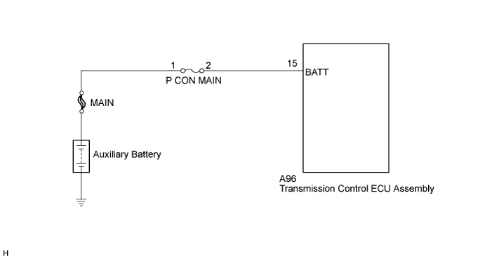
Auxiliary battery voltage is constantly applied to terminal BATT. This voltage is used to power the transmission control ECU memory. The transmission control ECU stores this DTC when it detects a malfunction related to terminal BATT.
Tech Tips
When there is an open or short in the BATT circuit, information on the actuator position (park (P) engaged or park (P) not engaged) stored in the transmission control ECU is cleared every time the power switch is turned off. Therefore, the ECU works to recognize the position each time the power switch is turned on (IG). As a result, the time from when the power switch is turned on (IG) until "READY ON" is indicated may become longer than normal.
| DTC No. | DTC Detection Condition | Trouble Area |
|---|---|---|
| C2310 | With the power switch on (IG) (IG circuit malfunction is not detected), voltage of transmission control ECU terminal BATT is 8 V or less for 1 second or more. |
|
WIRING DIAGRAM
INSPECTION PROCEDURE
PROCEDURE
-
INSPECT FUSE (P CON MAIN)
-
Remove the P CON MAIN fuse from the engine room junction block assembly.
-
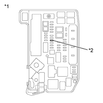
Text in Illustration *1 Engine Room Junction Block Assembly *2 P CON MAIN Fuse Measure the resistance according to the value(s) in the table below.
Standard Resistance Tester Connection Condition Specified Condition P CON MAIN fuse Always Below 1 Ω -
Install the P CON MAIN fuse.
NG 
REPLACE FUSE (P CON MAIN)
OK 
-
-
READ VALUE USING INTELLIGENT TESTER (BATTERY VOLTAGE VALUE)
-
Connect the intelligent tester to the DLC3.
-
Turn the power switch on (IG).
-
Enter the following menus: Chassis / Transmission Control / Data List / Battery Voltage Value.
-
Read the Data List displayed on the intelligent tester.
Result Tester Display Condition Specified Condition Battery Voltage Value Always 9 to 14 V -
Turn the power switch off.
NG 
CHECK HARNESS AND CONNECTOR (TRANSMISSION CONTROL ECU ASSEMBLY - P CON MAIN FUSE) Click here
OK 
REPLACE TRANSMISSION CONTROL ECU ASSEMBLY Click here
-
-
CHECK HARNESS AND CONNECTOR (TRANSMISSION CONTROL ECU ASSEMBLY - P CON MAIN FUSE)
-
Disconnect connector A96 from the transmission control ECU assembly connector.
-
Disconnect the P CON MAIN fuse from the engine room junction block assembly.
-
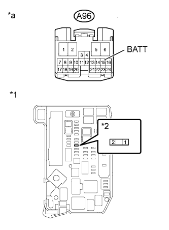
Text in Illustration *1 Engine Room Junction Block Assembly *2 P CON MAIN Fuse Connector of Engine Room Junction Block Assembly *a Front view of wire harness connector
(to Transmission Control ECU Assembly)
Measure the resistance according to the value(s) in the table below.
Standard Resistance (Check for Open) Tester Connection Switch Condition Specified Condition A96-15 (BATT) - 2 (P CON MAIN fuse) Power switch off Below 1 Ω Standard Resistance (Check for Short) Tester Connection Switch Condition Specified Condition A96-15 (BATT) or 2 (P CON MAIN fuse) - Body ground and other terminals Power switch off 10 kΩ or higher Note
Be careful not to break the fuse holder by forcing the tester probes into it during this inspection.
-
Install the P CON MAIN fuse.
-
Connect the transmission control ECU assembly connector.
NG
REPAIR OR REPLACE HARNESS OR CONNECTOR
OK
CHECK AND REPAIR POWER SOURCE CIRCUIT
-