STEERING KNUCKLE REMOVAL

Note
-
When the brake pedal is first depressed after replacing the brake pads or pushing back the disc brake piston, DTC C1214 may be output. As there is no malfunction, clear the DTC.
-
While the battery is connected, even if the power switch is off, the brake control system activates when the brake pedal is depressed or any door courtesy switch turns on. Therefore, when servicing brake system components, do not operate the brake pedal or open/close the doors while the battery is connected.
Tech Tips
-
Use the same procedure for the RH side and LH side.
-
The procedure listed below is for the LH side.
-
REMOVE FRONT AXLE ASSEMBLY
-
REMOVE FRONT LOWER BALL JOINT ASSEMBLY
-
Secure the front axle assembly in a vise.
Note
When using a vise, do not overtighten it.
-
Remove the cotter pin and nut.
-
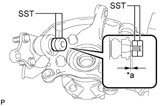
Text in Illustration *a 1mm Install SST to the front lower ball joint assembly as shown in the illustration.
- SST
- 09960-20010 ( 09961-02050, 09961-02050 )
Note
Check that the clearance measurement between SST and the front axle assembly is 1 mm (0.04 in.).
-
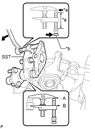
Text in Illustration *a Apply grease. *b Place the wrench here. Using SST, remove the front lower ball joint assembly from the front axle assembly as shown in the illustration.
- SST
- 09960-20010 ( 09961-02010, 09961-02050, 09961-02050 )
CAUTION:
Apply grease to the threads and end of the SST bolt.
Note
-
Install SST so that A and B are parallel.
-
Be sure to place the wrench on the part indicated in the illustration.
-
Do not damage the front lower ball joint dust cover.
-
-
REMOVE STEERING KNUCKLE
-
Secure the front axle assembly between aluminium plates in a vise.
Note
When using a vise, do not overtighten it.
-
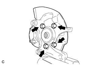
Remove the 4 bolts and front axle hub sub-assembly from the steering knuckle.
Note
Do not place the hub and bearing's magnet rotor side so that it is facing downward, and do not allow the magnet rotor side to become damaged or contact foreign matter.
-
Remove the front brake dust cover from the steering knuckle.
-