RADIATOR INSTALLATION
-
INSTALL RADIATOR ASSEMBLY
-
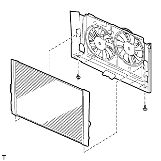
Install the fan shroud to the radiator assembly with the 2 bolts.
- Torque:
- 7.0 N*m { 71 kgf*cm, 62 in.*lbf }
-
Install the 2 lower radiator supports.
-
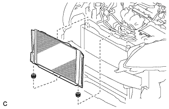
Install the radiator assembly with the fan shroud.
Note
Do not apply any excessive force to the cooler condenser assembly or pipe when installing the radiator assembly.
-
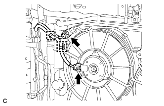
Connect the 2 wire harness clamps and 2 connectors.
-
-
INSTALL NO. 2 FAN SHROUD
-
Install the No. 2 fan shroud with the 2 bolts and 2 claws.
- Torque:
- 7.0 N*m { 71 kgf*cm, 62 in.*lbf }
-
-
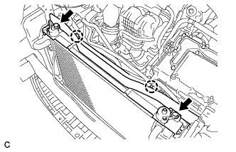
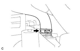
CONNECT NO. 5 INVERTER COOLING HOSE
-
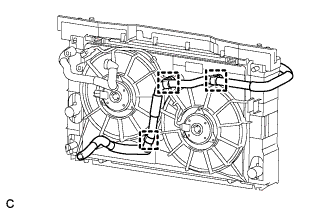
Connect the 3 clamps and No. 5 inverter cooling hose to the fan shroud.
-
-
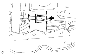
CONNECT NO. 3 WATER BY-PASS HOSE
-
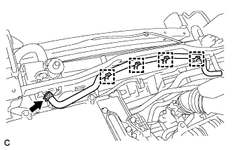
Connect the 4 clamps and No. 3 water by-pass hose.
-
-
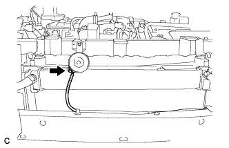
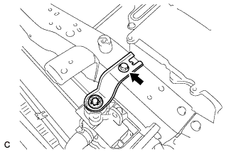
CONNECT WATER BY-PASS HOSE
-
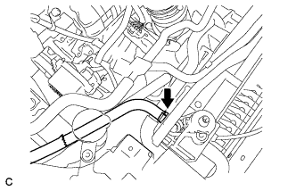
Connect the water by-pass hose.
-
-
INSTALL HOOD LOCK SUPPORT SUB-ASSEMBLY
-
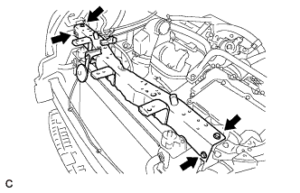
Install the hood lock support sub-assembly with the 4 bolts.
- Torque:
- 13 N*m { 133 kgf*cm, 10 ft.*lbf }
-
Connect the horn connector.
-
-
INSTALL HOOD LOCK ASSEMBLY (w/o Engine Hood Courtesy Switch)
-
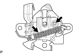
Apply MP grease to the sliding areas of the lock.
-
Install the hood lock assembly with the 3 bolts.
- Torque:
- 7.5 N*m { 77 kgf*cm, 66 in.*lbf }
-
Connect the hood lock control cable.
-
-
INSTALL HOOD LOCK ASSEMBLY (w/ Engine Hood Courtesy Switch)
-
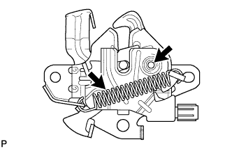
Apply MP grease to the sliding areas of the lock.
-
Install the hood lock assembly with the 3 bolts.
- Torque:
- 7.5 N*m { 77 kgf*cm, 66 in.*lbf }
-
Connect the hood lock control cable.
-
Connect the connector.
-
-
INSTALL RADIATOR SUPPORT RH
-
Install the radiator support cushion to the radiator support RH.
-
Install the radiator support RH with the bolt.
- Torque:
- 19 N*m { 194 kgf*cm, 14 ft.*lbf }
-
Connect the No. 2 water by-pass hose clamp to the radiator support RH.
-
-
INSTALL RADIATOR SUPPORT LH
-
Install the radiator support cushion to the radiator support LH.
-
Install the radiator support LH with the bolt.
- Torque:
- 19 N*m { 194 kgf*cm, 14 ft.*lbf }
-
-
CONNECT NO. 2 RADIATOR HOSE
-
Connect the No. 2 radiator hose to the radiator assembly with the clamp.
-
-
CONNECT NO. 1 RADIATOR HOSE
-
Connect the No. 1 radiator hose to the radiator assembly with the clamp.
-
-
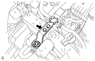
INSTALL NO. 1 INVERTER BRACKET
-
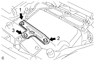
Temporarily install the No. 1 inverter bracket with the 3 bolts.
-
Tighten the 3 bolts in the order shown in the illustration.
- Torque:
- 14 N*m { 138 kgf*cm, 10 ft.*lbf }
-
-
INSTALL AIR CLEANER CASE
-
Install the air cleaner case with the 3 bolts.
- Torque:
- 7.0 N*m { 71 kgf*cm, 62 in.*lbf }
-
Install the hose to the 3 hose clamps.
-
Install the air cleaner filter element.
-
-
INSTALL INLET AIR CLEANER ASSEMBLY
-
Install the inlet air cleaner assembly with the 3 bolts.
- Torque:
- 7.0 N*m { 71 kgf*cm, 62 in.*lbf }
-
Connect the No. 4 water by-pass hose to the inlet air cleaner assembly with the clamp.
-
-
INSTALL AIR CLEANER CAP SUB-ASSEMBLY
-
Install the air cleaner cap sub-assembly with the 2 clamps.
-
Tighten the hose clamp.
-
Connect the mass air flow meter connector.
-
-
INSTALL FRONT BUMPER ASSEMBLY
-
Connect the 2 fog light connectors.
-
w/ Headlight Cleaner System:
-
Fill up washer jar with washer fluid Click here.
-
-
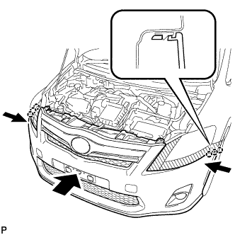
Engage the 6 claws and install the front bumper assembly.
-
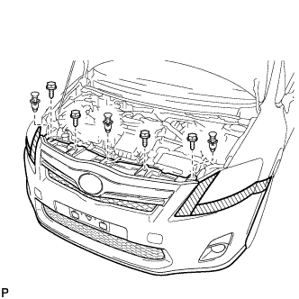
Install the 4 bolts and 3 clips.
-
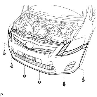
Install the 6 screws.
-
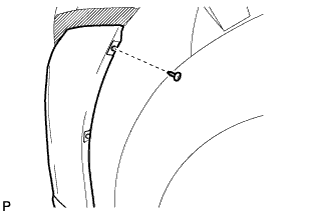
Install the clip.
Tech Tips
Use the same procedure for the RH side and LH side.
-
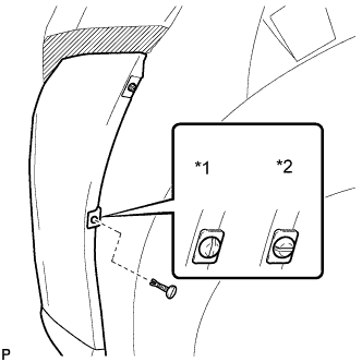
Text in Illustration *1 Correct *2 Incorrect Install the pin hold clip.
Note
Insert the pin hold clip with the slot aligned vertically. Do not rotate the clip after inserting it. After installation, confirm that the slot is vertical.
Tech Tips
Use the same procedure for the RH side and LH side.
-
Remove the protective tape.
-
-
ADD COOLANT (for Engine)
-
Tighten the radiator drain cock plug.
-
Connect the hose to the air release valve. (w/ Air Release Valve)
-
Loosen the air release valve. (w/ Air Release Valve)
-
Add TOYOTA Super Long Life Coolant (SLLC) to the reservoir tank filler opening until coolant overflows from the air release valve. Then tighten the air release valve. (w/ Air Release Valve)
-
Disconnect the hose from the air release valve. (w/ Air Release Valve)
-
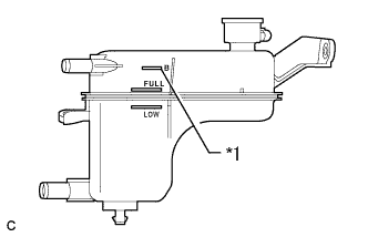
Text in Illustration *1 B Line Add TOYOTA Super Long Life Coolant (SLLC) to the B line on the reservoir tank.
Standard Capacity Item Capacity Engine coolant w/ Exhaust Heat Recirculation System:
7.2 liters (7.6 US qts, 6.3 lmp. qts)
w/o Exhaust Heat Recirculation System:
6.5 liters (6.8 US qts, 5.7 lmp. qts)
Tech Tips
TOYOTA vehicles are filled with TOYOTA SLLC at the factory. In order to avoid damage to the engine cooling system and other technical problems, only use TOYOTA SLLC or similar high quality ethylene glycol based non-silicate, non-amine, non-nitrite, non-borate coolant with long-life hybrid organic acid technology (coolant with long-life hybrid organic acid technology is a combination of low phosphates and organic acids).
Note
Never use water as a substitute for engine coolant.
-
Squeeze the inlet and outlet radiator hoses several times by hand, and then check the level of the coolant.
If the coolant level is low, add coolant.
-
Put the engine in inspection mode Click here.
-
Install the reservoir tank cap.
-
Bleed air from the cooling system.
Note
-
Before starting the engine, turn the A/C switch off.
-
Adjust the heater control to the maximum hot setting.
-
Adjust the blower speed to the low setting.
-
Warm up the engine until the thermostat opens. While the thermostat is open, allow the coolant to circulate for several minutes.
Tech Tips
The thermostat opening timing can be confirmed by squeezing the inlet radiator hose by hand, and sensing vibrations when the engine coolant starts to flow inside the hose.
CAUTION:
When squeezing the radiator hose:
-
Wear protective gloves.
-
Be careful as the radiator hoses are hot.
-
Keep your hands away from the radiator fan.
-
-
Squeeze the inlet and outlet radiator hoses several times by hand to bleed air from the system.
CAUTION:
When squeezing the radiator hose:
-
Wear protective gloves.
-
Be careful as the radiator hoses are hot.
-
Keep your hands away from the radiator fan.
-
-
-
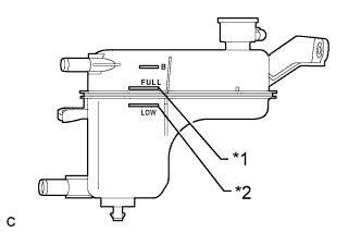
Text in Illustration *1 Full Line *2 Low Line After the engine has cooled down, check that the coolant level is between full and low lines.
If the coolant level is low, add coolant to the full line on the reservoir tank.
-
-
INSPECT FOR COOLANT LEAK (for Engine)
CAUTION:
Do not remove the reservoir tank cap while the engine and radiator are still hot. Pressurized, hot engine coolant and steam may be released and cause serious burns.
Note
Before performing each inspection, turn the A/C switch off.
-
Remove the reservoir tank cap.
-
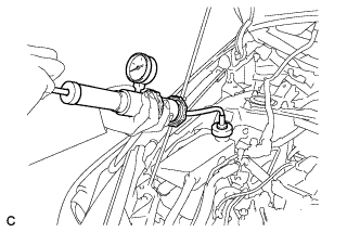
Fill the radiator and reservoir with coolant, and then attach a radiator cap tester.
-
Put the engine in inspection mode Click here.
-
Warm up the engine.
-
Using a radiator cap tester, increase the pressure inside the radiator to 108 kPa (1.1 kgf/cm2, 16 psi), and check that the pressure does not drop. If the pressure drops, check the hoses, radiator, front exhaust pipe assembly and the heater hose around and engine water pump assembly for leaks. If no external leaks are found, check the heater core, cylinder block and cylinder head.
-
Remove the radiator cap tester.
-
Install the reservoir tank cap.
-
-
INSTALL NO. 1 ENGINE UNDER COVER
-
CONNECT CABLE TO NEGATIVE BATTERY TERMINAL
Note
When disconnecting the cable, some systems need to be initialized after the cable is reconnected Click here.
-
INSTALL BATTERY BOX COVER
-
Engage the 3 guides to install the battery box cover.
-
-
INSTALL REAR DECK FLOOR BOX
-
Install the rear deck floor box.
-
-
INSTALL REAR FLOOR MAT
-
Install the rear floor mat.
-
-
ADJUST FOG LIGHT AIMING