FRAME WIRE REMOVAL
-
PRECAUTION
-
REMOVE REAR FLOOR MAT
-
Remove the rear floor mat.
-
-
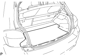
REMOVE REAR DECK FLOOR BOX
-
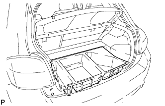
Remove the rear deck floor box.
-
-
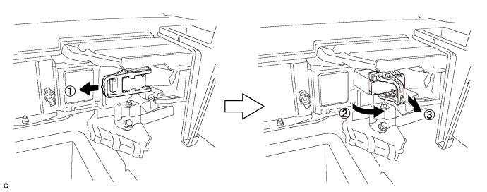
REMOVE BATTERY BOX COVER
-
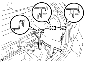
Disengage the 3 guides and remove the battery box cover.
-
-
DISCONNECT CABLE FROM NEGATIVE BATTERY TERMINAL
Note
When disconnecting the cable, some systems need to be initialized after the cable is reconnected Click here.
-
REMOVE SERVICE PLUG GRIP
CAUTION:
-
Wear insulating gloves.
-
Remove the service plug grip to interrupt the high voltage circuit at the time of inspection or repair.
-
Keep the removed service plug grip in your pocket to prevent other technicians from accidentally reconnecting it while you are servicing the vehicle.
-
All the high voltage wiring connectors are colored in orange.
-
Wear insulating gloves and remove the service plug grip after sliding up the lever of the service plug grip as shown in the illustration.
CAUTION:
-
Keep the removed service plug grip in your pocket to prevent other technicians from accidentally reconnecting it while you are servicing the vehicle.
-
After removing the service plug grip, do not touch the high voltage connectors or terminals for 10 minutes.
Tech Tips
Waiting for at least 10 minutes is required to discharge the high-voltage capacitor inside the inverter with converter assembly.
-
-
-
REMOVE INVERTER WITH CONVERTER ASSEMBLY
-
REMOVE FRONT EXHAUST PIPE ASSEMBLY
-
REMOVE FRONT NO. 1 FLOOR HEAT INSULATOR
-
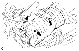
Remove the 3 nuts and front No. 1 floor heat insulator.
-
-
REMOVE FRONT FLOOR COVER RH
-
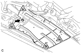
Remove the bolt
-
Remove the 4 clips and the front floor cover RH.
-
-
REMOVE FRONT CENTER FLOOR COVER RH
-

Remove the 3 clips and the front floor cover center RH.
-
-
REMOVE FRONT SUSPENSION MEMBER BRACE REAR RH
-
Using a transmission jack, hold the front suspension cross member.
Note
Be sure to position the transmission jack to properly support the front suspension cross member.
-
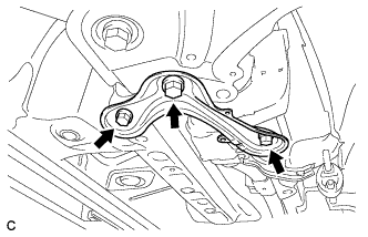
Remove the 3 bolts and front suspension member brace rear RH.
-
-
REMOVE PACKAGE TRAY TRIM PANEL ASSEMBLY
-
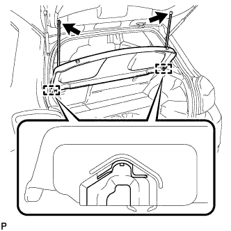
Disengage the 2 suspenders.
-
Disengage the 2 pins and remove the package tray trim panel assembly.
-
-
REMOVE DECK BOARD SUB-ASSEMBLY
-
Disengage the 3 claws and 3 clips, and remove the deck board sub-assembly.
-
-
REMOVE REAR NO. 1 FLOOR BOARD
-
Remove the bolt.
-
Disengage the 2 claws, 2 clips and 3 guides, and remove the rear No. 1 floor board.
-
-
REMOVE REAR SEAT ASSEMBLY LH
-
REMOVE REAR SEAT ASSEMBLY RH
-
REMOVE REAR DOOR SCUFF PLATE RH
Tech Tips
Use the same procedure described for the LH side Click here.
-
REMOVE REAR SEATBACK HINGE SUB-ASSEMBLY (for RH Side)
Tech Tips
Use the same procedure described for the LH side Click here.
-
REMOVE REAR SEAT SIDE GARNISH RH
-
Disengage the 6 claws and 2 clips, and remove the rear seat side garnish RH.
-
-
REMOVE REAR FLOOR BOARD SPACER
-
Remove the 2 clips and rear floor board spacer.
-
-
REMOVE NO. 1 HYBRID BATTERY EXHAUST DUCT
-
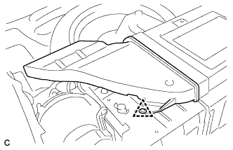
Remove the clip and No. 1 hybrid battery exhaust duct.
-
-
REMOVE UPPER HYBRID BATTERY COVER SUB-ASSEMBLY
CAUTION:
Be sure to wear insulated gloves and protective goggles.
-
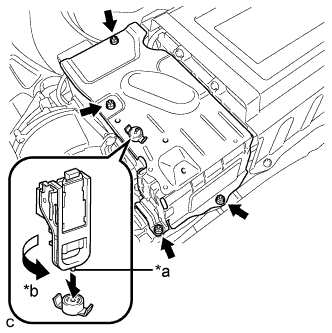
Text in Illustration *a Projection *b Turn Using the service plug grip, remove the battery cover lock striker.
Tech Tips
Insert the projection part of the service plug grip, and turn the button of the battery cover lock striker counterclockwise, and release the lock.
-
Remove the 4 nuts and upper hybrid battery cover sub-assembly.
-
-
REMOVE NO. 1 HYBRID BATTERY INTAKE DUCT
-
Remove the 2 clips and No. 1 hybrid battery intake duct.
-
-
DISCONNECT CABLE FROM BATTERY TERMINAL
-
Remove the connector cover.
-
Disconnect the clamp, and remove the nut.
-
Disconnect the 2 wire harness clamps.
-
-
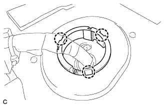
DISCONNECT HYBRID BATTERY JUNCTION BLOCK
CAUTION:
Wear insulating gloves.
Note
Insulate the removed terminals with insulating tape.
-
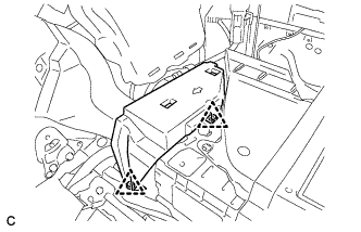
Remove the 2 nuts, then disconnect the frame wire from the hybrid battery junction block.
-
Disconnect the clamp and frame wire.
-
-
REMOVE FRAME WIRE
CAUTION:
Wear insulating gloves.
Note
Insulate the removed terminals with insulating tape.
-
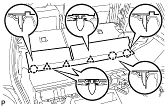
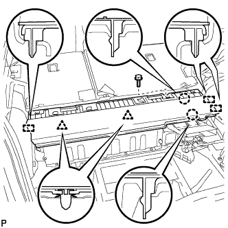
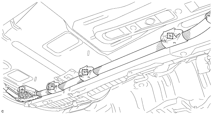
Disconnect the 3 wire harness clamps from the floor panel.
-
Disconnect the 3 claws and push the frame wire out from the floor panel.
-
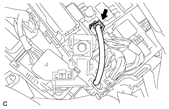
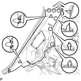
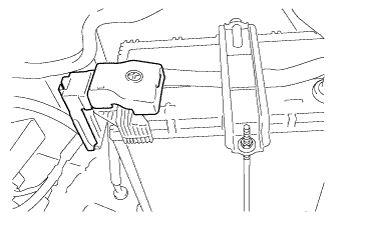
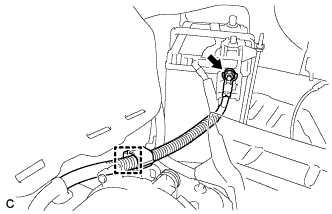
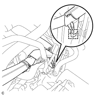
Disconnect the connector from the engine room junction block assembly.
-
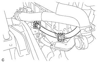
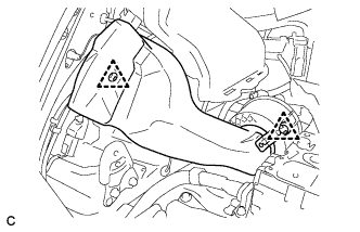
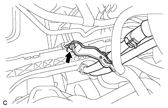
Disconnect the 2 clamps shown in the illustration.
-
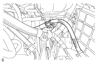
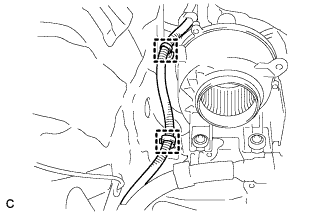
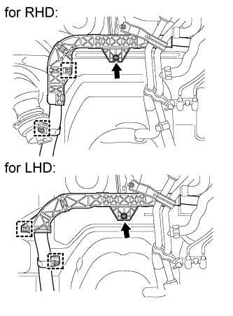
Disconnect the clamp shown in the illustration.
-
Disconnect the clamp shown in the illustration.
-
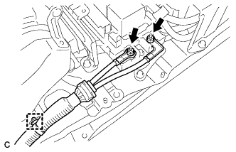
Remove the nut and heater water pipe sub-assembly.
-
Remove the nut and 2 clamps shown in the illustration.
-
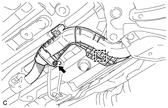
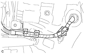
Remove the nut and clamp shown in the illustration.
-

Remove the nut shown in the illustration.
-
Remove the frame wire and the 4 clamps.
Note
The clamps are non-reusable parts.
-