HYBRID BATTERY SYSTEM, Diagnostic DTC:P0A9D-123, P0A9E-123, P0AC7-123, P0AC8-123, P0ACC-123, P0ACD-123
| DTC Code | DTC Name |
|---|---|
| P0A9D-123 | Hybrid Battery Temperature Sensor "A" Circuit Low |
| P0A9E-123 | Hybrid Battery Temperature Sensor "A" Circuit High |
| P0AC7-123 | Hybrid Battery Temperature Sensor "B" Circuit Low |
| P0AC8-123 | Hybrid Battery Temperature Sensor "B" Circuit High |
| P0ACC-123 | Hybrid Battery Temperature Sensor "C" Circuit Low |
| P0ACD-123 | Hybrid Battery Temperature Sensor "C" Circuit High |
DESCRIPTION
-
Refer to the description for DTC P0A9C-123 Click here.
| DTC No. | DTC Detection Condition | Trouble Area |
|---|---|---|
| P0A9D-123 P0A9E-123 P0AC7-123 P0AC8-123 P0ACC-123 P0ACD-123 |
When the temperature of the battery temperature sensor is less than the standard value (open) or higher than the standard value (shorted) (1 trip detection). |
|
Tech Tips
After confirming that a DTC is output, use the intelligent tester to check "Temp of BATT TB 1 to 3" in the hybrid vehicle control system ECU data list.
| Temperature Displayed | Malfunction |
|---|---|
| -45°C (-49°F) or less | Open or +B short circuit |
| 95°C (203°F) or more | GND short circuit |
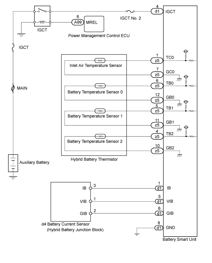
WIRING DIAGRAM
INSPECTION PROCEDURE
CAUTION:
-
Before inspecting the high-voltage system, take safety precautions to prevent electrical shocks, such as wearing insulated gloves and removing the service plug grip. After removing the service plug grip, put it in your pocket to prevent other technicians from accidentally reconnecting it while you are working on the high-voltage system.
-
After removing the service plug grip, wait for at least 10 minutes before touching any of the high-voltage connectors or terminals. After waiting for 10 minutes, check the voltage at the terminals in the inspection point in the inverter with converter assembly. The voltage should be 0 V before beginning work Click here.
Tech Tips
Waiting for at least 10 minutes is required to discharge the high-voltage capacitor inside the inverter with converter assembly.
PROCEDURE
-
CHECK DTC OUTPUT (HV)
-
Connect the intelligent tester to the DLC3.
-
Turn the power switch on (IG).
-
Enter the following menus: Powertrain / Hybrid Control / Trouble Codes.
-
Check if DTCs are output.
Result Result Proceed to P0AFC-123 is not output. A P0AFC-123 is also output. B -
Turn the power switch off.
B 
GO TO DTC CHART Click here
A 
-
-
READ VALUE USING INTELLIGENT TESTER
-
Connect the intelligent tester to the DLC3.
-
Turn the power switch on (IG).
-
Enter the following menus: Powertrain / Hybrid Control / Data List / Temp of Batt TB 1 to 3.
Tech Tips
Compare the temperature of the 3 battery temperature sensors to determine the sensor with the malfunction (Temp of Batt TB1 to TB3).
NEXT
-
-
CHECK CONNECTOR CONNECTION CONDITION
CAUTION:
Be sure to wear insulated gloves.
-
Check that the service plug grip is not installed.
Note
After removing the service plug grip, do not turn the power switch on (READY), unless instructed by the repair manual because this may cause a malfunction.
-
Remove the No. 1 hybrid vehicle battery carrier bracket sub-assembly Click here.
-
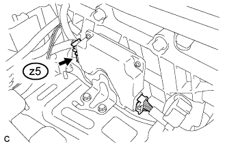
Check the connections of connector z5 of the battery smart unit.
OK The connectors are connected securely and there are no contact problems. -
Install the No. 1 hybrid vehicle battery carrier bracket sub-assembly Click here.
NG
CONNECT SECURELY
OK
-
-
CHECK HYBRID BATTERY THERMISTOR (BATTERY TEMPERATURE SENSOR)
CAUTION:
Be sure to wear insulated gloves.
-
Check that the service plug grip is not installed.
Note
After removing the service plug grip, do not turn the power switch on (READY), unless instructed by the repair manual because this may cause a malfunction.
-
Remove the No. 1 hybrid vehicle battery carrier bracket sub-assembly Click here.
-
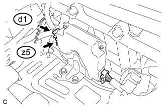
Disconnect connectors z5 and d1 from the battery smart unit.
-
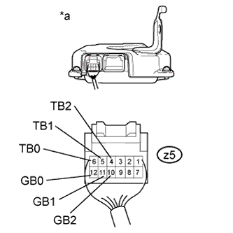
Text in Illustration *a Rear view of wire harness connector
(to Battery Smart Unit)
Measure the resistance of the circuit for the malfunctioning sensor (battery temperature sensor 0 to 2).
Tester Connection Tester Connection Battery Temperature Sensor No. z5-6 (TB0) - z5-12 (GB0) 0 z5-5 (TB1) - z5-11 (GB1) 1 z5-4 (TB2) - z5-10 (GB2) 2 Standard Resistance Thermistor Temperature Switch Condition Specified Condition 0°C (32°F) Power switch off 26.7 to 27.8 kΩ 25°C (77°F) Power switch off 9.9 to 10.1 kΩ 40°C (104°F) Power switch off 5.73 to 5.92 kΩ -
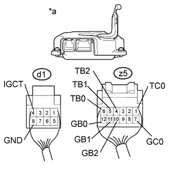
Text in Illustration *a Rear view of wire harness connector
(to Battery Smart Unit)
Measure the resistance according to the value(s) in the table below.
Standard Resistance Tester Connection Switch Condition Standard Resistance z5-6 (TB0) - d1-4 (IGCT) Power switch off 10 kΩ or higher z5-6 (TB0) - d1-8 (GND) Power switch off 10 kΩ or higher z5-12 (GB0) - d1-4 (IGCT) Power switch off 10 kΩ or higher z5-12 (GB0) - d1-8 (GND) Power switch off 10 kΩ or higher z5-5 (TB1) - d1-4 (IGCT) Power switch off 10 kΩ or higher z5-5 (TB1) - d1-8 (GND) Power switch off 10 kΩ or higher z5-11 (GB1) - d1-4 (IGCT) Power switch off 10 kΩ or higher z5-11 (GB1) - d1-8 (GND) Power switch off 10 kΩ or higher z5-4 (TB2) - d1-4 (IGCT) Power switch off 10 kΩ or higher z5-4 (TB2) - d1-8 (GND) Power switch off 10 kΩ or higher z5-10 (GB2) - d1-4 (IGCT) Power switch off 10 kΩ or higher z5-10 (GB2) - d1-8 (GND) Power switch off 10 kΩ or higher z5-1 (TC0) - d1-4 (IGCT) Power switch off 10 kΩ or higher z5-1 (TC0) - d1-8 (GND) Power switch off 10 kΩ or higher z5-7 (GC0) - d1-4 (IGCT) Power switch off 10 kΩ or higher z5-7 (GC0) - d1-8 (GND) Power switch off 10 kΩ or higher -
Connect the battery smart unit connectors.
-
Install the No. 1 hybrid vehicle battery carrier bracket sub-assembly Click here.
NG 
OK
-
-
CHECK BATTERY SMART UNIT (VIB VOLTAGE)
Note
Be sure to wear insulated gloves.
-
Check that the service plug grip is not installed.
Note
After removing the service plug grip, do not turn the power switch on (READY), unless instructed by the repair manual because this may cause a malfunction.
-
Remove the No. 1 hybrid vehicle battery carrier bracket sub-assembly Click here.
-
Turn the power switch on (IG).
Note
Turning the power switch on (IG) with the service plug grip removed causes an interlock switch system DTC to be set. Use the intelligent tester to clear the DTCs Click here.
-
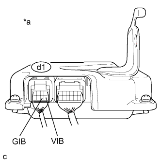
Text in Illustration *a Component with harness connected
(Battery Smart Unit)
Measure the voltage according to the value(s) in the table below.
Standard Voltage Tester Connection Switch Condition Specified Condition d1-5 (VIB) - d1-6 (GIB) Power switch on (IG) 4.6 to 5.4 V -
Turn the power switch off.
-
Install the No. 1 hybrid vehicle battery carrier bracket sub-assembly Click here.
NG
CHECK HYBRID BATTERY JUNCTION BLOCK Click here
OK 
REPLACE BATTERY SMART UNIT Click here
-
-
CHECK HYBRID BATTERY JUNCTION BLOCK
Note
Be sure to wear insulated gloves.
-
Check that the service plug grip is not installed.
Note
After removing the service plug grip, do not turn the power switch on (READY), unless instructed by the repair manual because this may cause a malfunction.
-
Remove the No. 1 hybrid vehicle battery carrier bracket sub-assembly Click here.
-
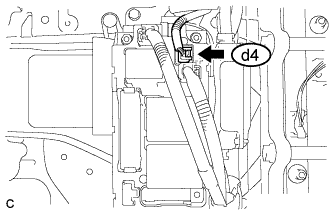
Disconnect connector d4 from the hybrid battery junction block.
-
Turn the power switch on (IG).
Note
If the power switch is turned on (IG) with the connector removed, DTCs will be stored. If the DTCs are output, clear the DTCs using the intelligent tester Click here.
-
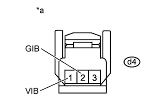
Text in Illustration *a Front view of wire harness connector
(to Hybrid Battery Junction Block)
Measure the voltage according to the value(s) in the table below.
Standard Voltage Tester Connection Switch Condition Specified Condition d4-1 (VIB) - d4-2 (GIB) Power switch on (IG) 4.6 to 5.4 V -
Turn the power switch off.
-
Connect the hybrid battery junction block connector.
-
Install the No. 1 hybrid vehicle battery carrier bracket sub-assembly Click here.
NG
CHECK HARNESS AND CONNECTOR (BATTERY SMART UNIT - HYBRID BATTERY JUNCTION BLOCK) Click here
OK
REPLACE HYBRID BATTERY JUNCTION BLOCK Click here
-
-
CHECK HARNESS AND CONNECTOR (BATTERY SMART UNIT - HYBRID BATTERY JUNCTION BLOCK)
Note
Be sure to wear insulated gloves.
-
Check that the service plug grip is not installed.
Note
After removing the service plug grip, do not turn the power switch on (READY), unless instructed by the repair manual because this may cause a malfunction.
-
Remove the No. 1 hybrid vehicle battery carrier bracket sub-assembly Click here.
-
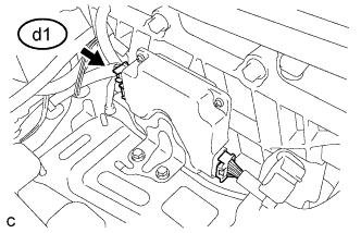
Disconnect connector d1 from the battery smart unit.
-
Disconnect connector d4 from the hybrid battery junction block.
-
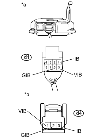
Text in Illustration *a Rear view of wire harness connector
(to Battery Smart Unit)
*b Front view of wire harness connector
(to Hybrid Battery Junction Block)
Measure the resistance according to the value(s) in the tables below.
Standard Resistance (Check for Open) Tester Connection Switch Condition Specified Condition d1-1 (IB) - d4-3 (IB) Power switch off Below 1 Ω d1-6 (GIB) - d4-2 (GIB) Power switch off Below 1 Ω d1-5 (VIB) - d4-1 (VIB) Power switch off Below 1 Ω Standard Resistance (Check for Short) Tester Connection Switch Condition Specified Condition d1-1 (IB) or d4-3 (IB) - Body ground and other terminals Power switch off 10 kΩ or higher d1-6 (GIB) or d4-2 (GIB) - Body ground and other terminals Power switch off 10 kΩ or higher d1-5 (VIB) or d4-1 (VIB) - Body ground and other terminals Power switch off 10 kΩ or higher -
Connect the battery smart unit connector.
-
Connect the hybrid battery junction block connector.
-
Install the No. 1 hybrid vehicle battery carrier bracket sub-assembly Click here.
NG
REPAIR OR REPLACE HARNESS OR CONNECTOR
OK
REPLACE BATTERY SMART UNIT Click here
-
-
CHECK HARNESS AND CONNECTOR (BATTERY TEMPERATURE SENSOR)
CAUTION:
Be sure to wear insulated gloves and protective goggles.
-
Check that the service plug grip is not installed.
Note
After removing the service plug grip, do not turn the power switch on (READY), unless instructed by the repair manual because this may cause a malfunction.
-
Remove the upper hybrid battery cover sub-assembly Click here.
-
Check the wire harness and connectors of the battery temperature sensor for abnormalities by sight and touch.
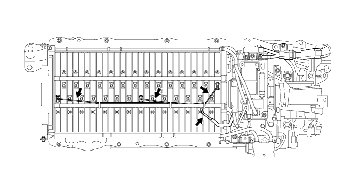
Specified Condition There are no open or short circuits in the wire harness and connectors. There are no short circuits to other wire harnesses. -
Install the upper hybrid battery cover sub-assembly Click here.
NG
REPAIR OR REPLACE HARNESS OR CONNECTOR
OK
REPLACE HYBRID BATTERY THERMISTOR Click here
-