HV BATTERY INSTALLATION
-
INSTALL NO. 2 HYBRID BATTERY PACK WIRE
-
Connect the 2 clamps and No. 2 hybrid battery pack wire.
-
-
INSTALL NO. 1 HYBRID BATTERY PACKING
CAUTION:
Be sure to wear insulated gloves and protective goggles.
Tech Tips
Perform this procedure only when replacement of the No. 1 hybrid battery packing is necessary.
-
Install the No. 1 hybrid battery packing with the 2 clamps.
-
-
INSTALL UPPER HYBRID BATTERY COVER SUB-ASSEMBLY
CAUTION:
Be sure to wear insulated gloves and protective goggles.
Tech Tips
Perform this procedure only when removal and installation of any parts under the upper hybrid battery cover sub-assembly is necessary.
-
Install the battery cover and No. 1 hybrid battery shield sub-assembly with the 3 bolts and 8 nuts.
- Torque:
- 7.5 N*m { 76 kgf*cm, 66 in.*lbf }
-
-
INSTALL NO. 1 HYBRID BATTERY COVER INTAKE DUCT
-
Install the No. 1 hybrid battery cover intake duct with the 2 clips.
-
-
INSTALL NO. 4 HYBRID VEHICLE BATTERY CARRIER BRACKET SUB-ASSEMBLY
CAUTION:
Wear insulated gloves.
-
Install the HV battery thermistor to the No. 4 hybrid vehicle battery carrier bracket sub-assembly.
-
Install the No. 4 hybrid vehicle battery carrier bracket sub-assembly with the 3 bolts.
- Torque:
- 7.5 N*m { 76 kgf*cm, 66 in.*lbf }
-
Connect the 3 wire harness clamps.
-
-
INSTALL NO. 1 HYBRID VEHICLE BATTERY CARRIER BRACKET SUB-ASSEMBLY
CAUTION:
Wear insulated gloves.
-
Text in Illustration *a Push Install the No. 1 hybrid vehicle battery carrier bracket sub-assembly with the 3 nuts.
- Torque:
- 7.5 N*m { 76 kgf*cm, 66 in.*lbf }
-
Install the battery cover lock striker, then push the button to lock it.
-
Install the electric vehicle battery plug assembly with the bolt as shown in the illustration.
- Torque:
- 7.5 N*m { 76 kgf*cm, 66 in.*lbf }
-
Connect the connector.
Note
The connector should be connected securely.
-
-
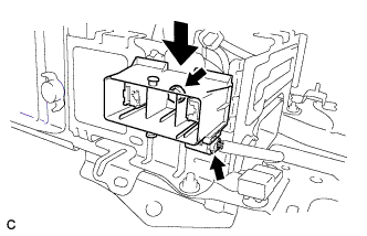
INSTALL BATTERY SMART UNIT
CAUTION:
Be sure to wear insulated gloves and protective goggles.
-
Install the battery smart unit with the 2 bolts.
- Torque:
- 7.5 N*m { 76 kgf*cm, 66 in.*lbf }
-
Connect the 3 connectors.
Note
The connectors should be connected securely.
-
-
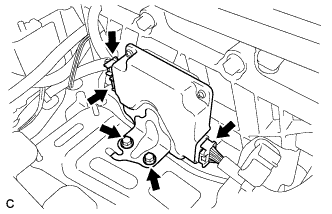
INSTALL HYBRID BATTERY JUNCTION BLOCK
-
Install the hybrid battery junction block with the 3 nuts.
- Torque:
- 7.5 N*m { 76 kgf*cm, 66 in.*lbf }
-
Connect the 2 connectors to the hybrid battery junction block.
Note
The connectors should be connected securely.
-
Connect the 2 connectors to the hybrid battery junction block.
Note
The connectors should be connected securely.
-
-
INSTALL HV BATTERY ASSEMBLY
CAUTION:
Wear insulated gloves.
Note
Use cardboard or other similar material to protect the HV battery and vehicle body from damage.
-
Install the HV battery to the vehicle with the 4 bolts.
- Torque:
- 19 N*m { 194 kgf*cm, 14 ft.*lbf }
-
Connect the connector and electrical key oscillator clamp.
-
-
INSTALL FRAME WIRE
CAUTION:
Wear insulating gloves.
-
Install the frame wire on the hybrid battery junction block with the 2 nuts.
- Torque:
- 9.0 N*m { 92 kgf*cm, 80 in.*lbf }
Note
-
Make sure that the ends of the frame wire are not crossed over each other.
-
Be sure to connect the frame wires to the correct terminals.
-
Connect the clamp and frame wire.
-
-
CHECK HIGH VOLTAGE CABLE CONNECTION CONDITION
CAUTION:
Wear insulated gloves and protective goggles.
-
Check that each wire harness is being installed securely.
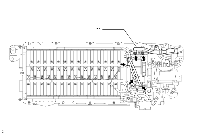
Text in Illustration *1 Frame Wire Note
-
Make sure that the end of the frame wire are not crossover each other.
-
Be sure to connect the frame wire to the correct terminals as shown in the illustration.
-
The connectors should be connected securely.
-
The nuts should be fastened securely.
-
Make sure that the 4 plastic covers are engaged securely.
-
-
-
INSTALL CROSS ANCHOR BRACKET SUB-ASSEMBLY LH
-
Install the cross anchor bracket sub-assembly LH with the 2 bolts.
- Torque:
- 37 N*m { 377 kgf*cm, 27 ft.*lbf }
-
-
INSTALL CROSS ANCHOR BRACKET SUB-ASSEMBLY RH
-
Connect the wire harness protector clamp.
-
Install the cross anchor bracket sub-assembly RH with the 2 bolts.
- Torque:
- 37 N*m { 377 kgf*cm, 27 ft.*lbf }
-
-
INSTALL REAR CENTER SEAT BACK HINGE SUB-ASSEMBLY
-
Install the rear center seat back hinge sub-assembly with the 2 bolts.
- Torque:
- 37 N*m { 377 kgf*cm, 27 ft.*lbf }
-
-
INSTALL NO. 7 HYBRID VEHICLE BATTERY UPPER CARRIER BRACKET
-
Install the No. 7 hybrid battery upper carrier bracket with the bolt.
- Torque:
- 7.5 N*m { 76 kgf*cm, 66 in.*lbf }
-
-
INSTALL BATTERY COOLING BLOWER ASSEMBLY
Note
-
Be sure not to touch the fan part of the battery cooling blower assembly.
-
Do not lift the battery cooling blower assembly using the wire harness.
-
Install the battery cooling blower assembly with the 2 bolts and nut
- Torque:
- 7.5 N*m { 76 kgf*cm, 66 in.*lbf }
-
Connect the battery cooling blower assembly connector and clamp.
-
Connect the 3 wire harness clamps.
-
-
INSTALL NO. 1 HYBRID BATTERY INTAKE DUCT
Note
Ensure that the duct is installed securely.
-
Install the No. 1 hybrid battery intake duct with the 2 clips.
-
-
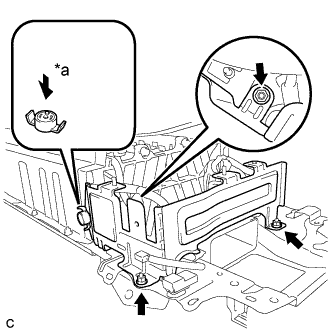
INSTALL UPPER HYBRID BATTERY COVER SUB-ASSEMBLY
-
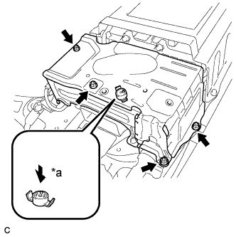
Text in Illustration *a Push Install the upper hybrid battery cover sub-assembly with the 4 nuts.
- Torque:
- 7.5 N*m { 76 kgf*cm, 66 in.*lbf }
-
Install the battery cover lock striker, then push the button to lock.
-
-
INSTALL HYBRID BATTERY COVER SHEET
-
Install the 2 hybrid battery cover sheet.
-
-
INSTALL NO. 1 HYBRID BATTERY EXHAUST DUCT
-
Insert the No. 1 hybrid battery exhaust duct with the clip.
Note
Ensure that the duct is installed securely.
-
-
INSTALL REAR FLOOR BOARD SPACER
-
Install the rear floor board spacer with the 2 clips.
-
-
INSTALL REAR SEAT SIDE GARNISH RH
-
Engage the 6 claws and 2 clips, and install the rear seat side garnish RH.
-
-
INSTALL REAR SEATBACK HINGE SUB-ASSEMBLY (for LH Side)
-
Install the rear seatback hinge sub-assembly with the bolt.
- Torque:
- 18 N*m { 185 kgf*cm, 13 ft.*lbf }
-
-
INSTALL REAR SEATBACK HINGE SUB-ASSEMBLY (for RH Side)
Tech Tips
Use the same procedure described for the LH side.
-
INSTALL REAR DOOR SCUFF PLATE RH
Tech Tips
Use the same procedure described for the LH side Click here.
-
INSTALL REAR SEAT ASSEMBLY LH
-
INSTALL REAR SEAT ASSEMBLY RH
-
INSTALL REAR NO. 1 FLOOR BOARD
-
Engage the 2 claws, 2 clips and 3 guides.
-
Install the rear No. 1 floor board with the bolt.
-
-
INSTALL NO. 6 BATTERY CARRIER PANEL
-
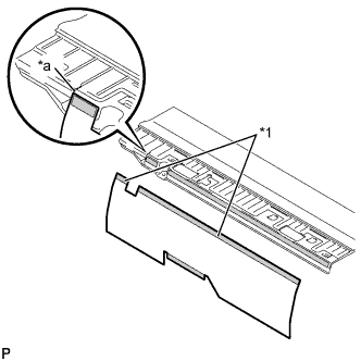
Text in Illustration *1 Double-sided tape *a Installation position guide Using the installation position guide shown in the illustration as a base, attach a new No. 6 battery carrier panel to the rear No. 1 floor board.
-
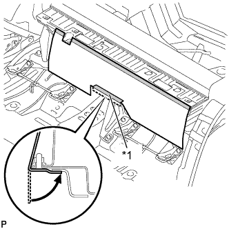
Text in Illustration *1 Double-sided tape Install the No. 6 battery carrier panel as shown in the illustration.
-
-
INSTALL DECK BOARD SUB-ASSEMBLY
-
Engage the 3 claws and 3 clips to install the deck board sub-assembly.
-
-
INSTALL PACKAGE TRAY TRIM PANEL ASSEMBLY
-
Engage the 2 pins.
-
Connect the 2 suspenders and install the package tray trim panel assembly.
-
-
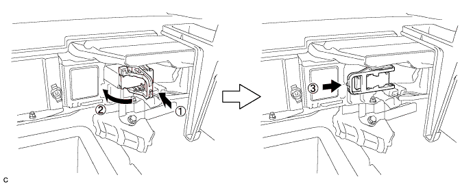
INSTALL SERVICE PLUG GRIP
CAUTION:
Wear insulating gloves.
Note
Before connecting the service plug, check that no parts and tools remain and that the high voltage terminals and connectors are connected securely.
-
Wear insulated gloves and install the service plug grip in the order shown in the illustration.
-
Rotate the handle of the service plug grip 90° toward the battery and slide it in the direction shown by the arrow until a click sound is heard.
-
-
CONNECT CABLE TO NEGATIVE BATTERY TERMINAL
Note
When disconnecting the cable, some systems need to be initialized after the cable is reconnected Click here.
-
INSTALL BATTERY BOX COVER
-
Engage the 3 guides to install the battery box cover.
-
-
INSTALL REAR DECK FLOOR BOX
-
Install the rear deck floor box.
-
-
INSTALL REAR FLOOR MAT
-
Install the rear floor mat.
-