HAZARD WARNING SWITCH INSPECTION
-
INSPECT HAZARD WARNING SIGNAL SWITCH ASSEMBLY
-
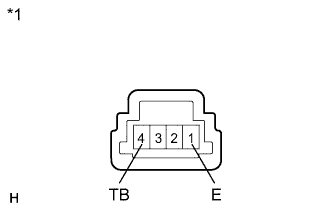
Text in Illustration *1 Component without harness connected
(Hazard Warning Signal Switch Assembly)
Measure the resistance according to the value(s) in the table below.
Standard resistance Tester Connection Switch Condition Specified Condition 4 (TB) - 1 (E) ON Below 1 Ω OFF 10 kΩ or higher If the result is not as specified, replace the switch.
-
Connect a (+) lead from the battery to terminal 3 and a (-) lead to terminal 2.
-
Check that the illumination of the switch comes on.
OK The illumination comes on. If the result is not as specified, replace the hazard warning signal switch assembly.
-