WIPER SWITCH INSTALLATION
-
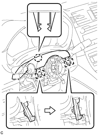
INSTALL WINDSHIELD WIPER SWITCH ASSEMBLY
-
Engage the claw and install the windshield wiper switch assembly as shown in the illustration.
-
Connect the 2 connectors.
-
-
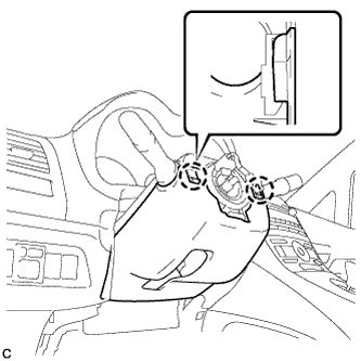
INSTALL UPPER STEERING COLUMN COVER
-
Engage the 2 claws and 2 pins to install the upper steering column cover.
-
-
INSTALL LOWER STEERING COLUMN COVER
Note
If the steering column cover is installed in the incorrect order, it will not be possible to assemble the steering column cover.
-
Engage the 2 claws to temporarily install the lower steering column cover.
-
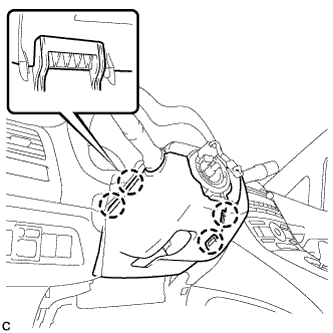
Engage the 4 claws.
-
Engage the 2 claws.
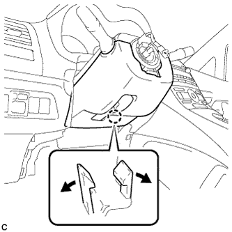
Tech Tips
Spread the claw and press the area around the claw to engage it.
-
-
TURN FRONT WHEELS TO FACE STRAIGHT AHEAD
-
ADJUST SPIRAL CABLE
-
Check that the power switch is off.
-
Check that the cable is disconnected from the negative (-) battery terminal.
CAUTION:
Wait at least 90 seconds after disconnecting the cable from the negative (-) battery terminal to disable the SRS system.
-
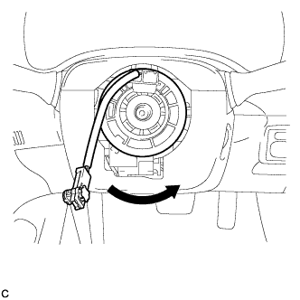
Rotate the spiral cable counterclockwise slowly by hand until it feels firm.
Note
Do not turn the spiral cable by the airbag wire harness.
-
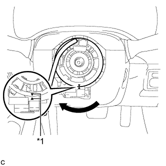
Text in Illustration *1 Alignment Mark Rotate the spiral cable clockwise approximately 2.5 turns to align the marks.
Note
Do not turn the spiral cable by the airbag wire harness.
Tech Tips
The spiral cable will rotate approximately 2.5 turns to both the left and right from the center.
-
-
INSTALL STEERING WHEEL ASSEMBLY
-
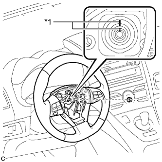
Text in Illustration *1 Matchmark Align the matchmarks on the steering wheel assembly and steering main shaft.
-
Install the steering wheel assembly set nut.
- Torque:
- 50 N*m { 510 kgf*cm, 37 ft.*lbf }
-
Connect the connectors to the spiral cable sub-assembly.
-
-
INSPECT STEERING WHEEL CENTER POINT
-
INSTALL STEERING PAD
-
INSTALL DRIVER SIDE KNEE AIRBAG ASSEMBLY
-
Check that the power switch is off.
-
Check that the cable is disconnected from the negative (-) battery terminal.
CAUTION:
Wait at least 90 seconds after disconnecting the cable from the negative (-) battery terminal to disable the SRS system.
-
Connect the driver side knee airbag connector.
Note
When connecting any airbag connector, take care not to damage the airbag wire harness.
-
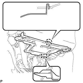
Engage the 6 claws and 2 guides.
-
Temporarily install the driver side knee airbag assembly with the 2 bolts (upper side).
-
Temporarily install the driver side knee airbag assembly with the 2 bolts (lower side).
-
Install the driver side knee airbag assembly with the 4 bolts.
- Torque:
- 10 N*m { 102 kgf*cm, 7 ft.*lbf }
-
-
INSTALL NO. 1 INSTRUMENT PANEL UNDER COVER SUB-ASSEMBLY
-
Engage the guide.
-
Engage the claw.
-
Install the No. 1 instrument panel under cover sub-assembly with the 2 screws <C> or <D>.
-