WIPER SWITCH REMOVAL

-
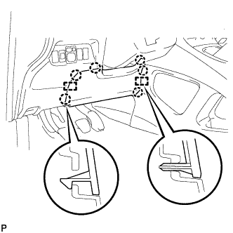
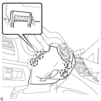
REMOVE NO. 1 INSTRUMENT PANEL UNDER COVER SUB-ASSEMBLY
-
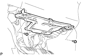
Remove the 2 screws <C> or <D>.
-
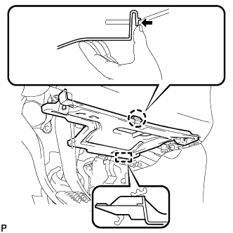
Disengage the claw and guide, and remove the No. 1 instrument panel under cover sub-assembly.
-
-
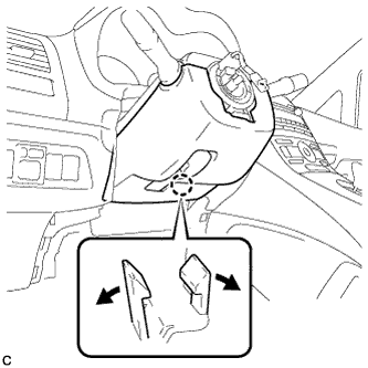
REMOVE DRIVER SIDE KNEE AIRBAG ASSEMBLY
CAUTION:
When storing the driver side knee airbag assembly, keep the airbag deployment side facing upward.
-
Check that the power switch is off.
-
Check that the cable is disconnected from the negative (-) battery terminal.
CAUTION:
Wait at least 90 seconds after disconnecting the cable from the negative (-) battery terminal to disable the SRS system.
-
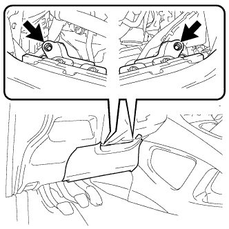
Remove the 2 bolts (upper side).
-
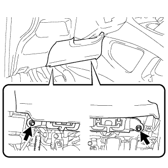
Remove the 2 bolts (lower side).
-
Disengage the 6 claws and 2 guides.
-
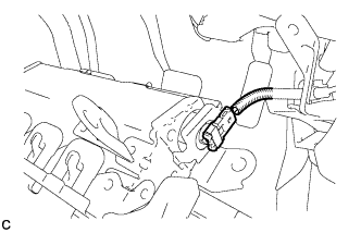
Disconnect the connector to remove the driver side knee airbag assembly.
Note
When disconnecting any airbag connector, take care not to damage the airbag wire harness.
-
-
REMOVE STEERING PAD
-
TURN FRONT WHEELS TO FACE STRAIGHT AHEAD
-
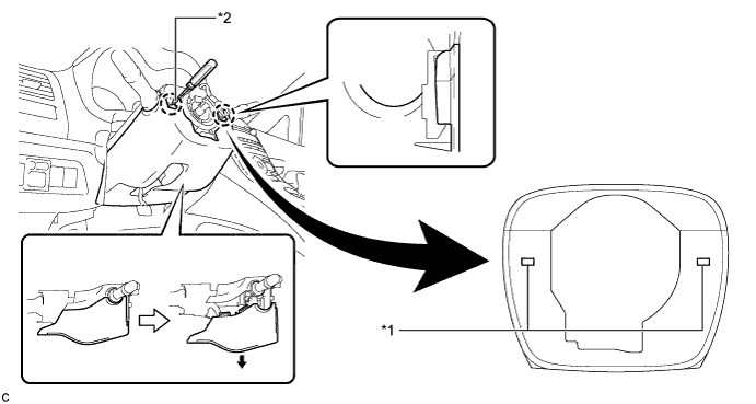
REMOVE STEERING WHEEL ASSEMBLY
-
Fully extend and tilt up the steering wheel.
-
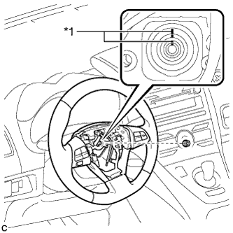
Text in Illustration *1 Matchmark Remove the steering wheel assembly set nut.
-
Put matchmarks on the steering wheel assembly and the steering main shaft.
-
Disconnect the connectors from the spiral cable.
-
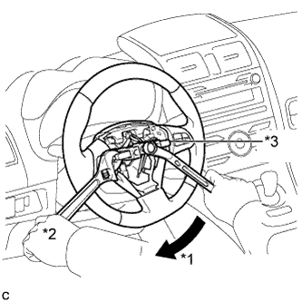
Text in Illustration *1 Turn *2 Hold *3 SST Using SST, remove the steering wheel assembly.
- SST
- 09950-50013 ( 09951-05010, 09952-05010, 09953-05020, 09954-05070 )
Note
Apply a small amount of grease to the threads and tip of SST (center bolt) before use.
-
-
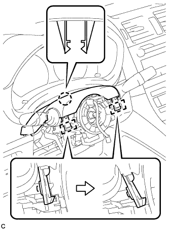
REMOVE LOWER STEERING COLUMN COVER
Note
Removing the lower steering column cover in the incorrect order will cause the lower steering column cover to break.
-
Push the right and left sides of the lower steering column cover, and disengage the 4 claws.
-
Insert fingers into the opening of the tilt lever of the lower steering column cover to disengage the 2 claws.
Tech Tips
Spread the claw to disengage it.
-
Using a screwdriver, insert the tip into each service hole to disengage the 2 claws to remove the lower steering column cover as shown in the illustration.
Text in Illustration *1 Service Hole *2 Protective Tape Tech Tips
Tape the screwdriver tip before use.
-
-
REMOVE UPPER STEERING COLUMN COVER
-
Disengage the 2 claws and 2 pins to remove the upper steering column cover.
-
-
REMOVE WINDSHIELD WIPER SWITCH ASSEMBLY
-
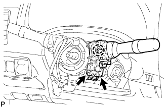
Disconnect the 2 connectors.
-
Disengage the claw and remove the windshield wiper switch assembly as shown in the illustration.
Note
If the claw is pushed with excessive force, it may break.
-