WIPER AND WASHER SYSTEM Front Wiper Motor Circuit
DESCRIPTION
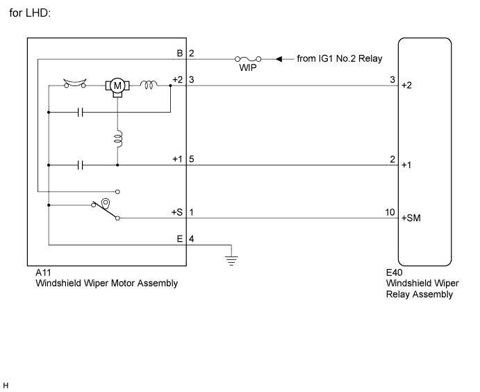
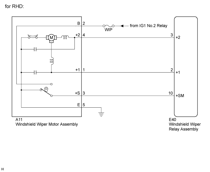
The windshield wiper relay assembly controls the windshield wiper motor assembly.
WIRING DIAGRAM
INSPECTION PROCEDURE
Note
Inspect the fuses for circuits related to this system before performing the following inspection procedure.
PROCEDURE
-
INSPECT WINDSHIELD WIPER MOTOR ASSEMBLY
-
for LHD:
-
Remove the windshield wiper motor assembly Click here.
-
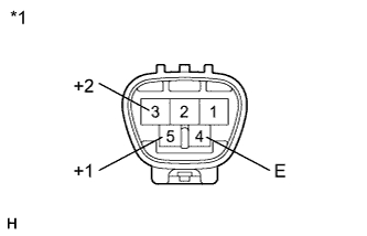
Text in Illustration *1 Component without harness connected
(Windshield Wiper Motor Assembly)
Check low speed operation.
Connect a battery positive (+) lead to terminal 5 (+1) and a negative (-) lead to terminal 4 (E), and check that the motor operates at low speed.
OK Motor operates at low speed. -
Check high speed operation.
Connect a battery positive (+) lead to terminal 3 (+2) and a negative (-) lead to terminal 4 (E), and check that the motor operates at high speed.
OK Motor operates at high speed.
-
-
for RHD:
-
Remove the windshield wiper motor assembly Click here.
-
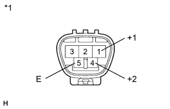
Text in Illustration *1 Component without harness connected
(Windshield Wiper Motor Assembly)
Check low speed operation.
Connect a battery positive (+) lead to terminal 1 (+1) and a negative (-) lead to terminal 5 (E), and check that the motor operates at low speed.
OK Motor operates at low speed. -
Check high speed operation.
Connect a battery positive (+) lead to terminal 4 (+2) and a negative (-) lead to terminal 5 (E), and check that the motor operates at high speed.
OK Motor operates at high speed.
-
NG 
REPLACE WINDSHIELD WIPER MOTOR ASSEMBLY Click here
OK 
-
-
CHECK HARNESS AND CONNECTOR (WINDSHIELD WIPER MOTOR ASSEMBLY - BATTERY AND BODY GROUND)
-
for LHD:
-
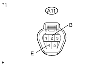
Text in Illustration *1 Front view of wire harness connector
(to Windshield Wiper Motor Assembly)
Disconnect the A11 windshield wiper motor assembly connector.
-
Measure the voltage according to the value(s) in the table below.
Standard Voltage Tester Connection Condition Specified Condition A11-2 (B) - Body ground Power switch on (IG) 11 to 14 V -
Measure the resistance according to the value(s) in the table below.
Standard Resistance Tester Connection Condition Specified Condition A11-4 (E) - Body ground Always Below 1 Ω
-
-
for RHD:
-
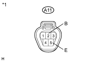
Text in Illustration *1 Front view of wire harness connector
(to Windshield Wiper Motor Assembly)
Disconnect the A11 windshield wiper motor assembly connector.
-
Measure the voltage according to the value(s) in the table below.
Standard Voltage Tester Connection Condition Specified Condition A11-2 (B) - Body ground Power switch on (IG) 11 to 14 V -
Measure the resistance according to the value(s) in the table below.
Standard Resistance Tester Connection Condition Specified Condition A11-5 (E) - Body ground Always Below 1 Ω
-
NG
REPAIR OR REPLACE HARNESS OR CONNECTOR
OK
-
-
CHECK HARNESS AND CONNECTOR (WINDSHIELD WIPER MOTOR - WINDSHIELD WIPER RELAY)
-
for LHD:
-
Disconnect the E40 windshield wiper relay assembly connector.
-
Measure the resistance according to the value(s) in the table below.
Standard Resistance Tester Connection Condition Specified Condition A11-5 (+1) - E40-2 (+1) Always Below 1 Ω A11-5 (+1) - Body ground Always 10 kΩ or higher A11-3 (+2) - E40-3 (+2) Always Below 1 Ω A11-3 (+2) - Body ground Always 10 kΩ or higher A11-1 (+S) - E40-10 (+SM) Always Below 1 Ω A11-1 (+S) - Body ground Always 10 kΩ or higher
-
-
for RHD:
-
Disconnect the E40 windshield wiper relay assembly connector.
-
Measure the resistance according to the value(s) in the table below.
Standard Resistance Tester Connection Condition Specified Condition A11-1 (+1) - E40-2 (+1) Always Below 1 Ω A11-1 (+1) - Body ground Always 10 kΩ or higher A11-4 (+2) - E40-3 (+2) Always Below 1 Ω A11-4 (+2) - Body ground Always 10 kΩ or higher A11-3 (+S) - E40-10 (+SM) Always Below 1 Ω A11-3 (+S) - Body ground Always 10 kΩ or higher
-
NG
REPAIR OR REPLACE HARNESS OR CONNECTOR
OK 
PROCEED TO NEXT SUSPECTED AREA SHOWN IN PROBLEM SYMPTOMS TABLE Click here
-