LOWER INSTRUMENT PANEL REMOVAL

-
PRECAUTION
-
ALIGN FRONT WHEELS FACING STRAIGHT AHEAD
-
REMOVE REAR FLOOR MAT
-
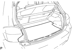
Remove the rear floor mat.
-
-
REMOVE REAR DECK FLOOR BOX
-
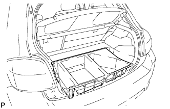
Remove the rear deck floor box.
-
-
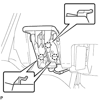
REMOVE BATTERY BOX COVER
-
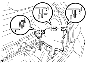
Disengage the 3 guides and remove the battery box cover.
-
-
DISCONNECT CABLE FROM NEGATIVE BATTERY TERMINAL
CAUTION:
Wait at least 90 seconds after disconnecting the cable from the negative (-) battery terminal to disable the SRS system.
Note
When disconnecting the cable, some systems need to be initialized after the cable is reconnected Click here.
-
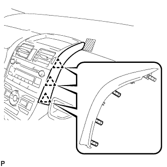
REMOVE INSTRUMENT CLUSTER FINISH PANEL ASSEMBLY
-
Operate the tilt lever to lower the steering wheel assembly.
-
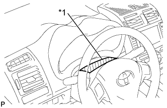
Text in Illustration *1 Protective Tape Apply protective tape to the area shown in the illustration.
-
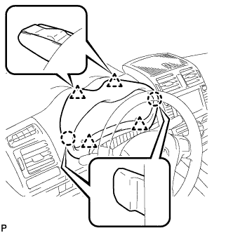
Disengage the 2 claws and 4 clips, and then remove the instrument cluster finish panel assembly.
-
-
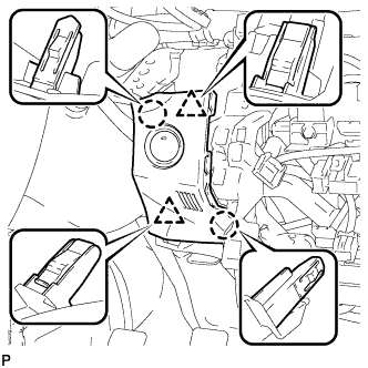
REMOVE COMBINATION METER ASSEMBLY
-
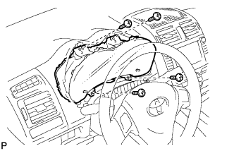
Remove the 4 screws.
-
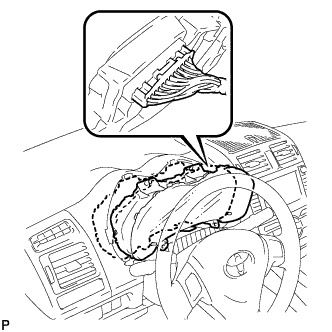
Pull the combination meter assembly, disconnect the connector, and remove the combination meter assembly.
Note
When removing the combination meter assembly, do not damage the upper instrument panel sub-assembly or combination meter assembly.
-
-
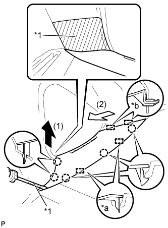
REMOVE INSTRUMENT PANEL FINISH PANEL END LH
-
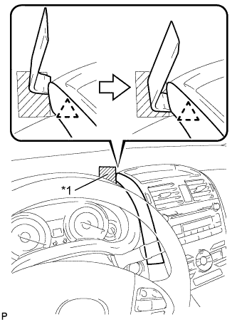
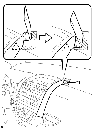
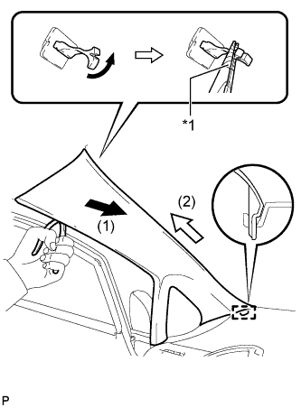
Text in Illustration *1 Protective Tape Apply protective tape to the area shown in the illustration.
-
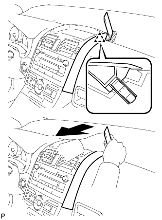
Insert a roof moulding remover and slide the remover toward the clip.
-
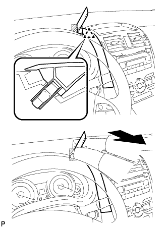
Pull the remover with both hands to disengage the clip as shown in the illustration.
-
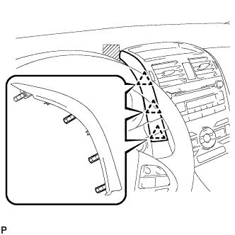
Disengage the 3 clips and remove the instrument panel finish panel end LH.
-
-
REMOVE INSTRUMENT PANEL FINISH PANEL END RH
-
Text in Illustration *1 Protective Tape Apply protective tape to the area shown in the illustration.
-
Insert a roof moulding remover and slide the remover toward the clip.
-
Pull the remover with both hands to disengage the clip as shown in the illustration.
-
Disengage the 3 clips and remove the instrument panel finish panel end RH.
-
-
REMOVE CENTER INSTRUMENT PANEL REGISTER ASSEMBLY
-
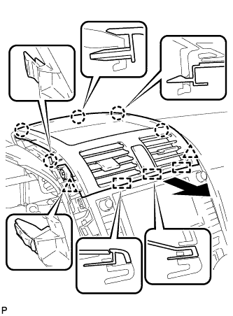
Disengage the 5 claws, 2 clips, and 3 guides.
-
Disconnect the connector and remove the center instrument panel register assembly.
-
-
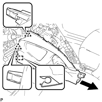
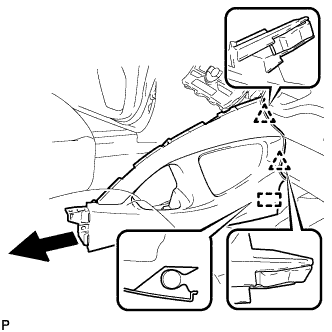
REMOVE FRONT PILLAR GARNISH CORNER PIECE LH
-
Text in Illustration *1 Protective Tape *a Guide (A) *b Guide (B) Apply protective tape to the areas shown in the illustration.
-
Using a screwdriver, disengage the 5 claws and 2 guides (A).
Tech Tips
Tape the screwdriver tip before use.
-
Disengage the 2 guides (B) and remove the front pillar garnish corner piece LH.
-
-
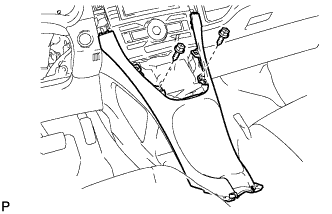
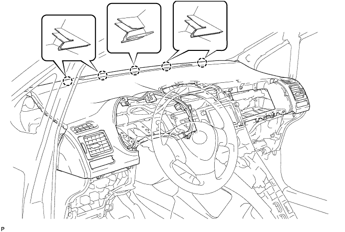
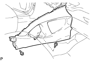
REMOVE FRONT PILLAR GARNISH LH
-
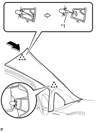
Text in Illustration *1 Front Pillar Garnish Clip Pull the upper part of the garnish toward the inside of the cabin and disengage the garnish from the base of the 2 clips.
Tech Tips
Make the front pillar garnish LH hang down from the front pillar garnish clip.
-
Text in Illustration *1 Protective Tape Turn the end of the front pillar garnish clip 90° with needle-nosed pliers and remove it from the front pillar garnish LH.
Note
-
Front pillar garnish clips are reusable if they are not removed from the vehicle and have no damage.
-
Replace the front pillar garnish clips with new ones if they are removed from the vehicle.
Tech Tips
Tape the tips of the needle-nosed pliers before use.
-
-
Disengage the guide at the front end of the front pillar garnish LH and remove it.
-
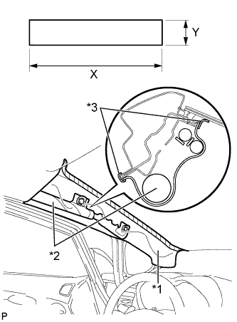
Text in Illustration *1 Protective Cover *2 Curtain Shield Airbag Assembly *3 Adhesive Tape Protect the curtain shield airbag assembly.
Protective Cover Size X 700 mm (27.56 in.) Y 120 mm (4.72 in.)
-
Cover the airbag with a 700 mm (27.56 in.) x 120 mm (4.72 in.) cloth or piece of nylon and fix the ends of the cover with tape as shown in the illustration.
Note
Cover the curtain shield airbag with a protective cover as soon as the front pillar garnish is removed.
-
-
-
REMOVE FRONT PILLAR GARNISH CORNER PIECE RH
Tech Tips
Use the same procedure as for the LH side.
-
REMOVE FRONT PILLAR GARNISH RH
Tech Tips
Use the same procedure as for the LH side.
-
REMOVE REAR CONSOLE BOX COVER
-
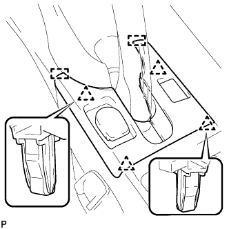
Disengage the 4 clips.
-
Disengage the 2 guides.
-
Disconnect the connector and remove the rear console box cover.
-
-
REMOVE UPPER CONSOLE PANEL
-
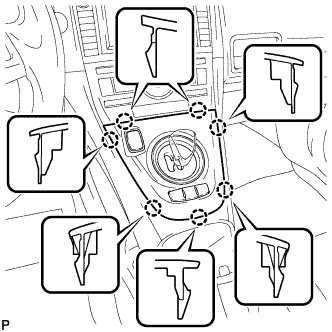
Disengage the 7 claws.
-
Disconnect the connector and remove the upper console panel.
-
-
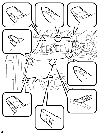
REMOVE LOWER CENTER INSTRUMENT PANEL FINISH PANEL
-
Remove the 2 screws <E> or <F>.
-
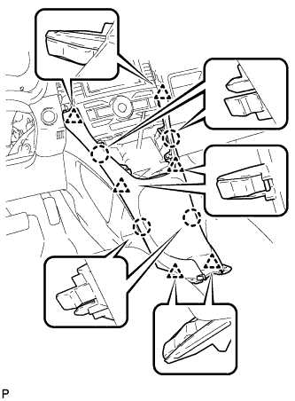
Disengage the 4 claws and 6 clips, and remove the lower center instrument panel finish panel.
-
-
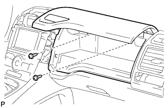
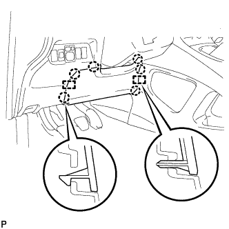
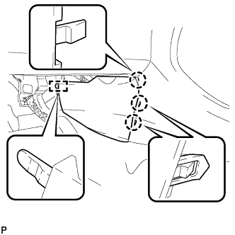
REMOVE GLOVE COMPARTMENT DOOR ASSEMBLY
-
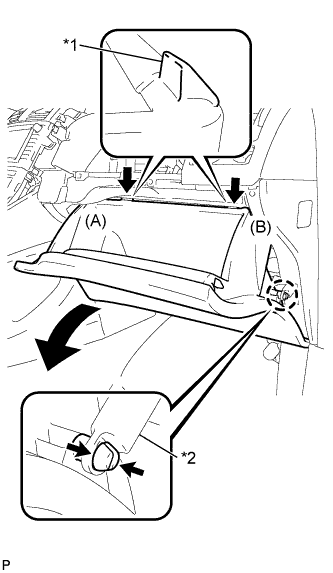
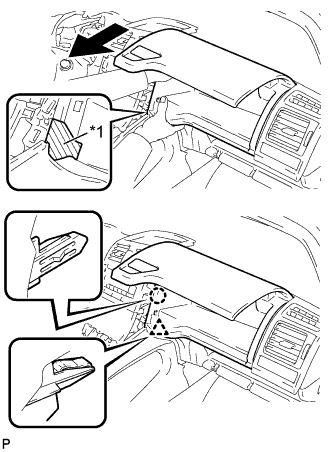
Text in Illustration *1 Stopper *2 Glove Compartment Door Stopper Disengage the claw and release the glove compartment door stopper.
-
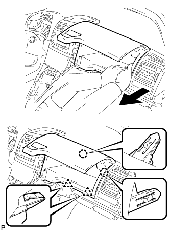
Bend portions (A) and (B) in the direction indicated by the arrows in the illustration to release the 2 stoppers, and lower the glove compartment door assembly until the front of the door is level.
-
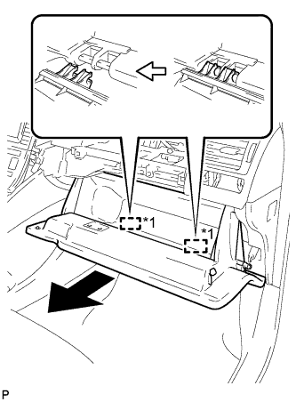
Text in Illustration *1 Hinge Pull the glove compartment door assembly horizontally toward the rear of the vehicle to release the 2 hinges, and remove the glove compartment door assembly.
Note
Pulling the glove compartment door assembly upward to remove it will cause the hinges to deform when reinstalling the door. Be sure to pull out the compartment door horizontally.
-
-
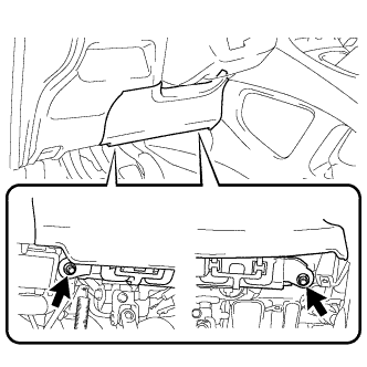
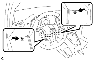
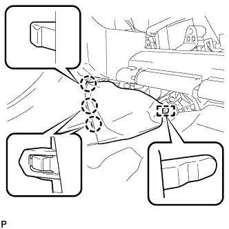
REMOVE NO. 1 INSTRUMENT PANEL BOX DOOR SUB-ASSEMBLY
-
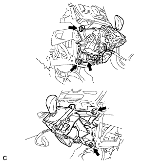
Remove the 2 screws <C> or <D>.
-
Text in Illustration *1 Protective Tape Apply protective tape to the area shown in the illustration.
-
Disengage the claw and clip.
-
Disengage the 2 claws and 2 clips.
-
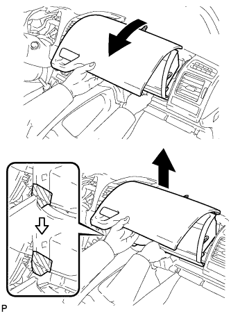
As shown in the illustration, remove the No. 1 instrument panel box door sub-assembly.
-
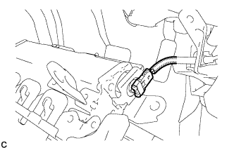
w/ USB Audio System:
-
Disengage the clamp and disconnect the connector.
-
-
-
DISCONNECT INSTRUMENT PANEL WIRE ASSEMBLY
-
Check that the power switch is off.
-
Check that the cable is disconnected from the negative (-) battery terminal.
CAUTION:
Wait at least 90 seconds after disconnecting the cable from the negative (-) battery terminal to disable the SRS system.
-
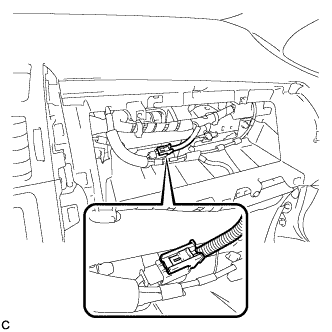
Disconnect the connector.
Note
When disconnecting any airbag connector, take care not to damage the airbag wire harness.
-
-
REMOVE UPPER INSTRUMENT PANEL SUB-ASSEMBLY
-
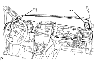
Text in Illustration *1 Protective Tape Apply protective tape to the areas shown in the illustration.
-
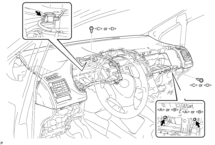
Operate the tilt lever to lower the steering wheel assembly.
-
Disconnect the connector.
-
Remove the 2 screws <C> or <D>.
-
Remove the 2 passenger airbag bolts <A> or <B>.
-
Disengage the 4 clips and 3 claws.
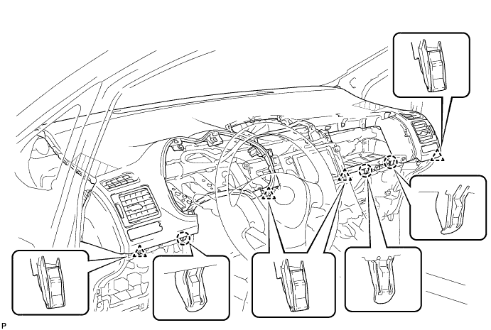
-
Disengage the 5 claws and remove the upper instrument panel sub-assembly.
Note
When removing the upper instrument panel sub-assembly, be careful not to damage it or the steering wheel assembly.
-
-
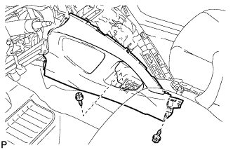
REMOVE NO. 1 INSTRUMENT PANEL UNDER COVER SUB-ASSEMBLY
-
Remove the 2 screws <C> or <D>.
-
Disengage the claw and guide, and remove the No. 1 instrument panel under cover sub-assembly.
-
-
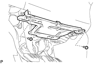
REMOVE DRIVER SIDE KNEE AIRBAG ASSEMBLY
CAUTION:
When storing the driver side knee airbag assembly, keep the airbag deployment side facing upward.
-
Check that the power switch is off.
-
Check that the cable is disconnected from the negative (-) battery terminal.
CAUTION:
Wait at least 90 seconds after disconnecting the cable from the negative (-) battery terminal to disable the SRS system.
-
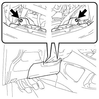
Remove the 2 bolts (upper side).
-
Remove the 2 bolts (lower side).
-
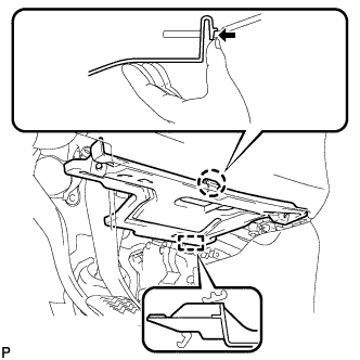
Disengage the 6 claws and 2 guides.
-
Disconnect the connector to remove the driver side knee airbag assembly.
Note
When disconnecting any airbag connector, take care not to damage the airbag wire harness.
-
-
REMOVE STEERING PAD
CAUTION:
When storing the steering pad, keep the airbag deployment side facing upward.
-
Check that the power switch is off.
-
Check that the cable is disconnected from the negative (-) battery terminal.
CAUTION:
Wait at least 90 seconds after disconnecting the cable from the negative (-) battery terminal to disable the SRS system.
-
Using a screwdriver, push the 2 torsional springs to disengage the 2 hooks.
Note
Do not drop the steering pad.
-
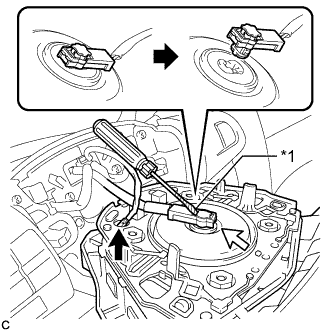
Text in Illustration *1 Protective Tape Pull out the steering pad from the steering wheel assembly and support the steering pad with one hand.
Note
When removing the steering pad, do not pull the airbag wire harness.
-
Disconnect the horn connector from the steering pad.
-
Using a screwdriver with its tip wrapped with protective tape, release the airbag connector lock.
-
Disconnect the airbag connector to remove the steering pad.
Note
When disconnecting any airbag connector, take care not to damage the airbag wire harness.
-
-
REMOVE STEERING WHEEL ASSEMBLY
-
Fully extend and tilt up the steering wheel.
-
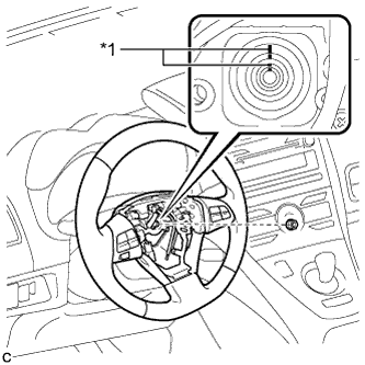
Text in Illustration *1 Matchmark Remove the steering wheel assembly set nut.
-
Put matchmarks on the steering wheel assembly and the steering main shaft.
-
Disconnect the connectors from the spiral cable.
-
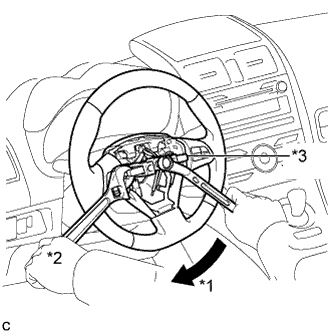
Text in Illustration *1 Turn *2 Hold *3 SST Using SST, remove the steering wheel assembly.
- SST
- 09950-50013 ( 09951-05010, 09952-05010, 09953-05020, 09954-05070 )
Note
Apply a small amount of grease to the threads and tip of SST (center bolt) before use.
-
-
REMOVE LOWER STEERING COLUMN COVER
Note
Removing the lower steering column cover in the incorrect order will cause the lower steering column cover to break.
-
Push the right and left sides of the lower steering column cover, and disengage the 4 claws.
-
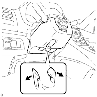
Insert fingers into the opening of the tilt lever of the lower steering column cover to disengage the 2 claws.
Tech Tips
Spread the claw to disengage it.
-
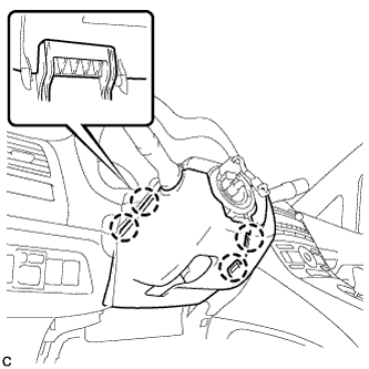
Using a screwdriver, insert the tip into each service hole to disengage the 2 claws to remove the lower steering column cover as shown in the illustration.
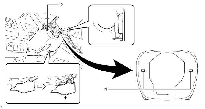
Text in Illustration *1 Service Hole *2 Protective Tape Tech Tips
Tape the screwdriver tip before use.
-
-
REMOVE UPPER STEERING COLUMN COVER
-
Disengage the 2 claws and 2 pins to remove the upper steering column cover.
-
-
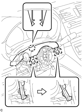
REMOVE TURN SIGNAL SWITCH ASSEMBLY WITH SPIRAL CABLE SUB-ASSEMBLY
-
Disconnect the connectors from the turn signal switch assembly with spiral cable sub-assembly.
-
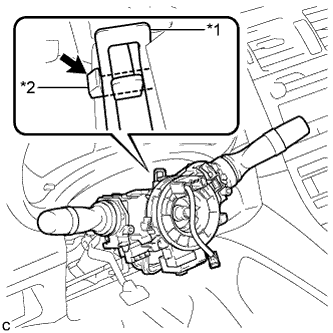
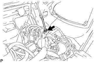
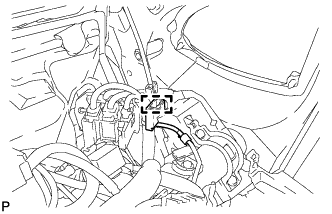
Text in Illustration *1 Clamp *2 Claw Using pliers, expand the clamp.
-
While holding the clamp expanded, raise the claw using a screwdriver to disengage it, and then remove the turn signal switch assembly with spiral cable sub-assembly from the steering column assembly.
-
-
REMOVE CENTER INSTRUMENT CLUSTER FINISH PANEL SUB-ASSEMBLY (w/o Radio Receiver)
-
Disengage the 4 clips and remove the center instrument cluster finish panel sub-assembly.
-
-
REMOVE RADIO RECEIVER OPENING COVER WITH BRACKET (w/o Radio Receiver)
-
Remove the 4 bolts <K> and remove the radio receiver opening cover with bracket.
-
-
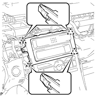
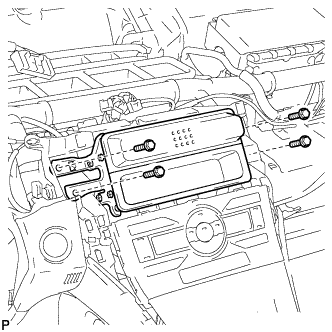
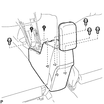
REMOVE RADIO RECEIVER WITH BRACKET (w/ Radio Receiver)
-
Remove the 4 bolts.
-
Pull the radio receiver with bracket toward the rear of the vehicle and disengage the 4 clips.
-
Disconnect each connector and remove the radio receiver with bracket.
-
-
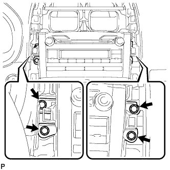
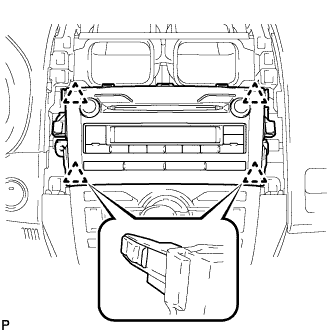
REMOVE NAVIGATION RECEIVER WITH BRACKET (w/ Navigation System)
-
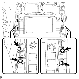
Remove the 4 bolts.
-
Pull the navigation receiver with bracket toward the rear of the vehicle and disengage the 4 clips.
-
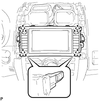
Disconnect each connector and remove the navigation receiver with bracket.
-
-
REMOVE AIR CONDITIONING CONTROL ASSEMBLY
-
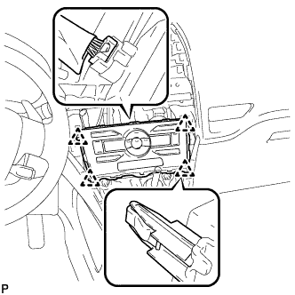
Disengage the 4 clips and remove the air conditioning control assembly.
-
Disconnect the connector.
-
-
REMOVE CONSOLE BOX CARPET
-
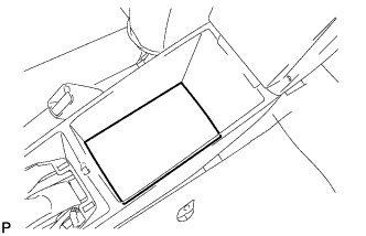
Remove the console box carpet.
-
-
REMOVE REAR CONSOLE BOX ASSEMBLY
-
Remove the 4 bolts and 2 screws.
-

Disengage the 4 claws and remove the rear console box assembly.
-
-
REMOVE FRONT DOOR SCUFF PLATE LH
-
Disengage the 10 claws and remove the front door scuff plate LH.
-
-
REMOVE COWL SIDE TRIM BOARD LH
-

Disengage the 2 clips.
-
Disengage the guide and remove the cowl side trim board LH.
-
-
REMOVE FRONT DOOR SCUFF PLATE RH
Tech Tips
Use the same procedure as for the LH side.
-
REMOVE COWL SIDE TRIM BOARD RH
Tech Tips
Use the same procedure as for the LH side.
-
REMOVE NO. 2 INSTRUMENT PANEL UNDER COVER SUB-ASSEMBLY
-
Disengage the 3 claws.
-
Disengage the guide and remove the No. 2 instrument panel under cover sub-assembly.
-
-
REMOVE FUSE BOX OPENING COVER
-
Disengage the 4 claws and 4 clips.
-
Disconnect each connector and then remove the fuse box opening cover.
-
-
REMOVE FRONT NO. 1 CONSOLE BOX INSERT
-
Disengage the 3 claws.
-
Disengage the guide and remove the front No. 1 console box insert.
-
-
REMOVE FRONT NO. 2 CONSOLE BOX INSERT
-
Disengage the 3 claws.
-
Disengage the guide and remove the front No. 2 console box insert.
-
-
REMOVE INSTRUMENT PANEL UNDER TRAY
-

Text in Illustration *1 Protective Tape Using a screwdriver, disengage the 4 claws and remove the instrument panel under tray.
Tech Tips
Tape the screwdriver tip before use.
-
-
REMOVE LOWER NO. 1 INSTRUMENT PANEL FINISH PANEL
-
Remove the 2 screws <E> or <F>.
-
Disengage the 4 claws and 2 guides.
-
Disengage the 2 clips and guide, and remove the lower No. 1 instrument panel finish panel.
-
-
REMOVE LOWER NO. 2 INSTRUMENT PANEL FINISH PANEL
-
Remove the 2 screws <E> or <F>.
-
Disengage the 2 clips and guide, and remove the lower No. 2 instrument panel finish panel.
-
-
REMOVE NO. 1 SWITCH HOLE BASE
-
Disengage the 2 claws and 2 clips.
-
Disconnect the connectors and remove the No. 1 switch hole base.
-
-
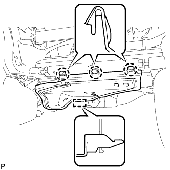
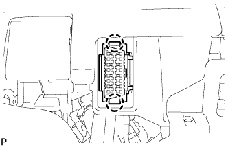
DISCONNECT TRANSMISSION INSTRUMENT PANEL SHIFT ASSEMBLY
-
Disconnect the connector and wire harness clamp from the transmission instrument panel shift assembly.
-
Remove the 4 nuts and transmission instrument panel shift assembly.
-
-
REMOVE ANTENNA CORD SUB-ASSEMBLY (for LHD)
-
Disconnect the connector.
-
Disengage the clamp.
-
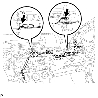
Text in Illustration *A w/o Radio Receiver Remove the bolt.
-
w/o Radio Receiver:
-
Disconnect the connector.
-
-
Disengage the 5 clamps and remove the antenna cord sub-assembly.
-
-
REMOVE ANTENNA CORD SUB-ASSEMBLY (for RHD)
-
Disconnect the connector.
-
Disengage the clamp.
-
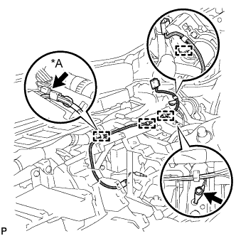
Text in Illustration *A w/o Radio Receiver Remove the bolt.
-
w/o Radio Receiver:
-
Disconnect the connector.
-
-
Disengage the 4 clamps and remove the antenna cord sub-assembly.
-
-
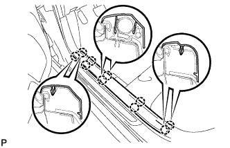
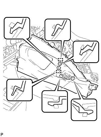
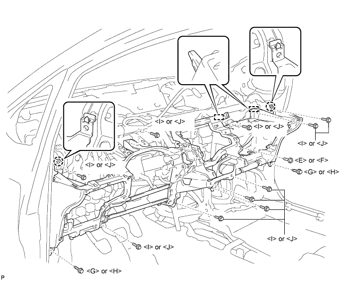
REMOVE LOWER INSTRUMENT PANEL SUB-ASSEMBLY
-
Disengage the 2 claws and DLC3.
-
Disengage the 3 claws and the hood lock control cable assembly.
-
Disengage each clamp.
-
Disconnect each connector.
-
Remove the 2 screws <E> or <F>.
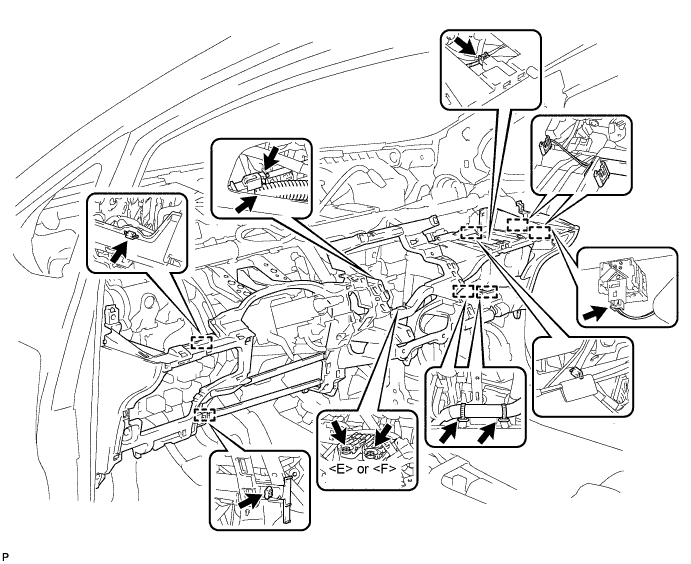
-
Remove the screw <E> or <F>.
-
Remove the 2 bolts <G> or <H>.
-
Remove the 10 screws <I> or <J>.
-
Disengage the 2 claws and 2 guides, and remove the lower instrument panel sub-assembly.
-