UPPER INSTRUMENT PANEL INSTALLATION
-
INSTALL UPPER INSTRUMENT PANEL SUB-ASSEMBLY
-
When using a new upper instrument panel sub-assembly:
-
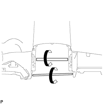
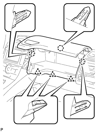
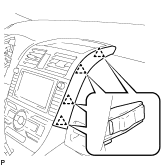
Immediately before installing the upper instrument panel sub-assembly, twist and cut off the portions shown in the illustration (joints for moulding).
-
-
When using a new upper instrument panel sub-assembly:
-
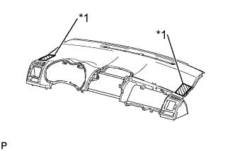
Text in Illustration *1 Protective Tape Apply protective tape to the areas shown in the illustration.
-
-
Engage the 5 claws.
Note
-
When installing the upper instrument panel sub-assembly, be careful not to damage it or the steering wheel assembly.
-
Do not allow the wire harness to get caught in the claws.
-
-
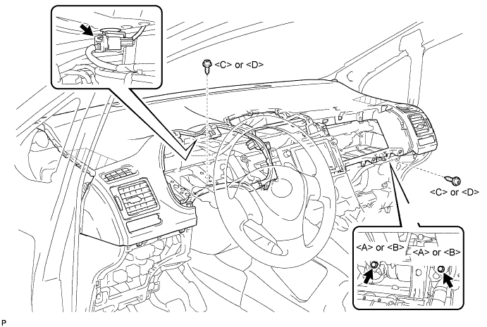
Engage the 3 claws and the 4 clips.
-
Install the 2 screws <C> or <D>.
-
Install the 2 passenger airbag bolts <A> or <B>.
- Torque:
- 20 N*m { 204 kgf*cm, 15 ft.*lbf }
-
Connect the connector and install the upper instrument panel sub-assembly.
-
Remove the protective tape.
-
-
CONNECT INSTRUMENT PANEL WIRE ASSEMBLY
-
Check that the power switch is off.
-
Check that the cable is disconnected from the negative (-) battery terminal.
CAUTION:
Wait at least 90 seconds after disconnecting the cable from the negative (-) battery terminal to disable the SRS system.
-
Connect the connector.
Note
When connecting any airbag connector, take care not to damage the airbag wire harness.
-
-
INSTALL NO. 1 INSTRUMENT PANEL BOX DOOR SUB-ASSEMBLY
-
w/ USB Audio System:
-
Connect the connector and engage the clamp.
-
-
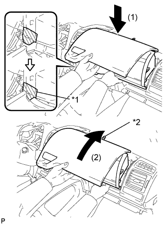
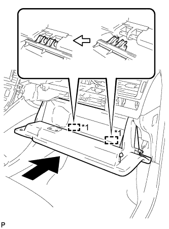
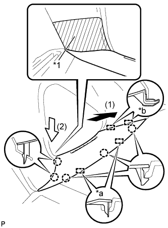
Text in Illustration *1 Protective Tape *2 Claw Apply protective tape to the area shown in the illustration.
-
Insert the instrument panel box assembly in the direction indicated by arrow (1) in the illustration so that the taped portion does not come in contact with the lower No. 1 instrument panel finish panel.
-
Push the instrument panel box assembly in the direction indicated by arrow (2) in the illustration so that the claw on the upper part of the instrument panel box assembly is inserted into the upper instrument panel sub-assembly.
-
Engage the 3 claws and 3 clips.
-
Install the No. 1 instrument panel box door sub-assembly with the 2 screws <C> or <D>.
-
-
INSTALL GLOVE COMPARTMENT DOOR ASSEMBLY
-
Text in Illustration *1 Hinge Insert the glove compartment door assembly horizontally and engage the 2 hinges.
Note
Engaging the hinges from the top will deform the hinges. Be sure to install the glove compartment door assembly horizontally.
-
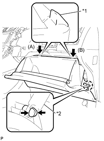
Text in Illustration *1 Stopper *2 Glove Compartment Door Stopper Bend portions (A) and (B) in the direction indicated by the arrows in the illustration to engage the 2 stoppers.
-
Engage the claw, connect the glove compartment door stopper, and install the glove compartment door assembly.
-
-
INSTALL LOWER CENTER INSTRUMENT PANEL FINISH PANEL
-
Engage the 4 claws and 6 clips.
-
Install the lower center instrument panel finish panel with the 2 screws <E> or <F>.
-
-
INSTALL UPPER CONSOLE PANEL
-
Engage the 7 claws and install the upper console panel.
-
-
INSTALL REAR CONSOLE BOX COVER
-
Connect the connector.
-
Engage the 2 guides and 4 clips to install the rear console box cover.
-
-
INSTALL FRONT PILLAR GARNISH LH
-
Remove the protective cover.
-
Text in Illustration *1 Protective Tape Make sure that the front pillar garnish clip is not damaged.
Note
-
If there is any damage, replace the garnish clip with a new one.
-
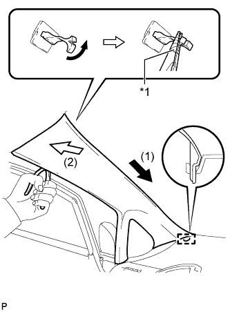
When a garnish clip is being replaced, make sure to install it in the direction shown in the illustration.
-
-
Engage the guide.
-
Turn the end of the front pillar garnish clip 90° with needle-nosed pliers and install it to the front pillar garnish LH.
Tech Tips
Tape the tips of the needle-nosed pliers before use.
-
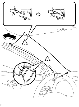
Engage the 2 clips to install the front pillar garnish LH.
-
-
INSTALL FRONT PILLAR GARNISH CORNER PIECE LH
-
Text in Illustration *1 Protective Tape *a Guide (A) *b Guide (B) Engage the 2 guides (B).
-
Engage the 2 guides (A) and 5 claws, then install the front pillar garnish corner piece LH.
-
Remove the protective tape.
-
-
INSTALL FRONT PILLAR GARNISH RH
Tech Tips
Use the same procedure as for the LH side.
-
INSTALL FRONT PILLAR GARNISH CORNER PIECE RH
Tech Tips
Use the same procedure as for the LH side.
-
INSTALL CENTER INSTRUMENT PANEL REGISTER ASSEMBLY
-
Connect the connector.
-
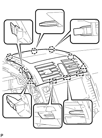
Engage the 3 guides, 5 claws and 2 clips, and install the center instrument panel register assembly.
-
-
INSTALL INSTRUMENT PANEL FINISH PANEL END LH
-
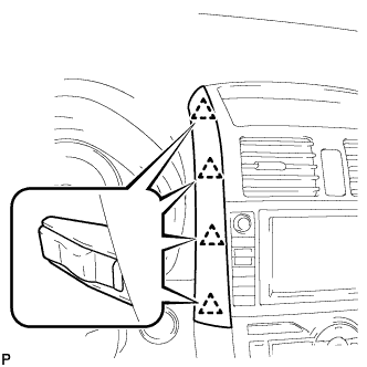
Engage the 4 clips and install the instrument panel finish panel end LH.
-
-
INSTALL INSTRUMENT PANEL FINISH PANEL END RH
-
Engage the 4 clips and install the instrument panel finish panel end RH.
-
-
INSTALL COMBINATION METER ASSEMBLY
-
Connect the connector and temporarily install the combination meter assembly.
Note
When installing the combination meter assembly, do not damage the upper instrument panel sub-assembly or combination meter assembly.
-
Install the combination meter assembly with the 4 screws.
-
-
INSTALL INSTRUMENT CLUSTER FINISH PANEL ASSEMBLY
-
Engage the 2 claws and 4 clips, and install the instrument cluster finish panel assembly.
-
Remove the applied protective tape on the steering column cover.
-
-
CONNECT CABLE TO NEGATIVE BATTERY TERMINAL
Note
When disconnecting the cable, some systems need to be initialized after the cable is reconnected Click here.
-
INSTALL BATTERY BOX COVER
-
Engage the 3 guides to install the battery box cover.
-
-
INSTALL REAR DECK FLOOR BOX
-
Install the rear deck floor box.
-
-
INSTALL REAR FLOOR MAT
-
Install the rear floor mat.
-
-
INSPECT SRS WARNING LIGHT