ROOM TEMPERATURE SENSOR INSTALLATION
-
INSTALL ROOM TEMPERATURE SENSOR
-
Engage the 2 claws and install the room temperature sensor.
-
Engage the air hose.
-
Connect the connector.
-
-
INSTALL NO. 1 SWITCH HOLE BASE
-
Connect the connectors.
-
Engage the 2 claws and 2 clips, and install the No. 1 switch hole base.
-
-
INSTALL LOWER NO. 1 INSTRUMENT PANEL FINISH PANEL
-
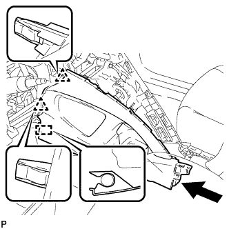
Engage the 2 clips and guide.
-
Engage the 4 claws and 2 guides.
-
Install the lower No. 1 instrument panel finish panel with the 2 screws <E> or <F>.
-
-
INSTALL INSTRUMENT PANEL UNDER TRAY
-
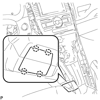
Engage the 4 claws and install the instrument panel under tray.
-
-
INSTALL FRONT NO. 1 CONSOLE BOX INSERT
-
Engage the guide.
-
Engage the 3 claws and install the front No. 1 console box insert.
-
-
INSTALL REAR CONSOLE BOX ASSEMBLY
-
Engage the 4 claws.
-
Install the rear console box assembly with the 4 bolts and 2 screws.
-
-
INSTALL CONSOLE BOX CARPET
-
Install the console box carpet.
-
-
INSTALL REAR CONSOLE BOX COVER
-
Connect the connector.
-
Engage the 2 guides and 4 clips to install the rear console box cover.
-
-
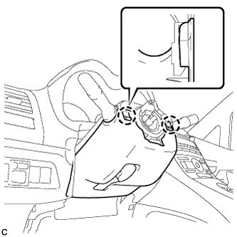
INSTALL UPPER STEERING COLUMN COVER
-
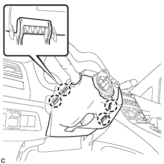
Engage the 2 claws and 2 pins to install the upper steering column cover.
-
-
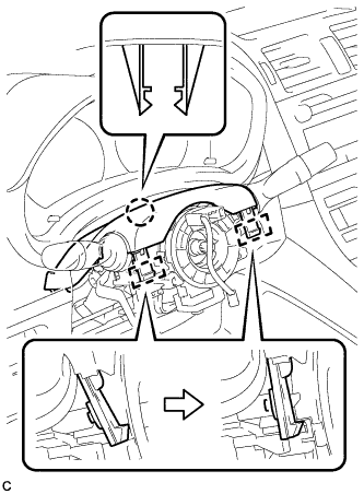
INSTALL LOWER STEERING COLUMN COVER
Note
If the steering column cover is installed in the incorrect order, it will not be possible to assemble the steering column cover.
-
Engage the 2 claws to temporarily install the lower steering column cover.
-
Engage the 4 claws.
-
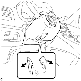
Engage the 2 claws.
Tech Tips
Spread the claw and press the area around the claw to engage it.
-
-
INSTALL STEERING WHEEL ASSEMBLY
-
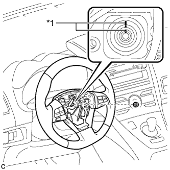
Text in Illustration *1 Matchmark Align the matchmarks on the steering wheel assembly and steering main shaft.
-
Install the steering wheel assembly set nut.
- Torque:
- 50 N*m { 510 kgf*cm, 37 ft.*lbf }
-
Connect the connectors to the spiral cable sub-assembly.
-
-
INSTALL STEERING PAD
-
Check that the power switch is off.
-
Check that the cable is disconnected from the negative (-) battery terminal.
CAUTION:
Wait at least 90 seconds after disconnecting the cable from the negative (-) battery terminal to disable the SRS system.
-
Connect the airbag connector to the steering pad.
Note
When connecting any airbag connector, take care not to damage the airbag wire harness.
-
Push in the lock to install the airbag connector.
-
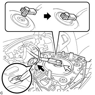
Connect the horn connector to the steering pad as shown in the illustration.
-
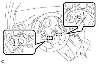
Push the steering pad to engage the 2 hooks.
Note
Make sure that the hooks are securely inserted into the steering pad holes.
-
-
INSTALL INSTRUMENT PANEL FINISH PANEL END LH
-
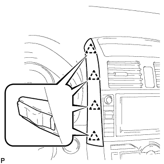
Engage the 4 clips and install the instrument panel finish panel end LH.
-
-
INSTALL INSTRUMENT CLUSTER FINISH PANEL ASSEMBLY
-
Engage the 2 claws and 4 clips, and install the instrument cluster finish panel assembly.
-
Remove the applied protective tape on the steering column cover.
-
-
INSPECT STEERING WHEEL CENTER POINT
-
INSPECT STEERING PAD
-
Make sure that the horn sounds.
Tech Tips
If the horn does not sound, inspect the horn system Click here.
-
-
INSPECT STEERING WHEEL CENTER POINT
-
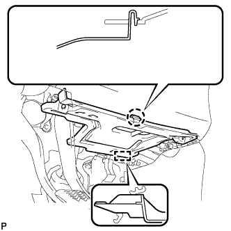
INSTALL DRIVER SIDE KNEE AIRBAG ASSEMBLY
-
Check that the power switch is off.
-
Check that the cable is disconnected from the negative (-) battery terminal.
CAUTION:
Wait at least 90 seconds after disconnecting the cable from the negative (-) battery terminal to disable the SRS system.
-
Connect the driver side knee airbag connector.
Note
When connecting any airbag connector, take care not to damage the airbag wire harness.
-
Engage the 6 claws and 2 guides.
-
Temporarily install the driver side knee airbag assembly with the 2 bolts (upper side).
-
Temporarily install the driver side knee airbag assembly with the 2 bolts (lower side).
-
Install the driver side knee airbag assembly with the 4 bolts.
- Torque:
- 10 N*m { 102 kgf*cm, 7 ft.*lbf }
-
-
INSTALL NO. 1 INSTRUMENT PANEL UNDER COVER SUB-ASSEMBLY
-
Engage the guide.
-
Engage the claw.
-
Install the No. 1 instrument panel under cover sub-assembly with the 2 screws <C> or <D>.
-
-
CONNECT CABLE TO NEGATIVE BATTERY TERMINAL
Tech Tips
When disconnecting the cable, some systems need to be initialized after the cable is reconnected Click here.
-
INSPECT SRS WARNING LIGHT