ROOF HEADLINING REASSEMBLY
-
INSTALL NO. 1 ROOF WIRE (w/ Sliding Roof)
-
Temporarily install the No. 1 roof wire aligned with the markings on the roof headlining assembly.
-
Turn the visor connectors clockwise approximately 90° to install the connectors to the roof headlining.
-
Apply adhesive tape to the locations shown in the illustration.
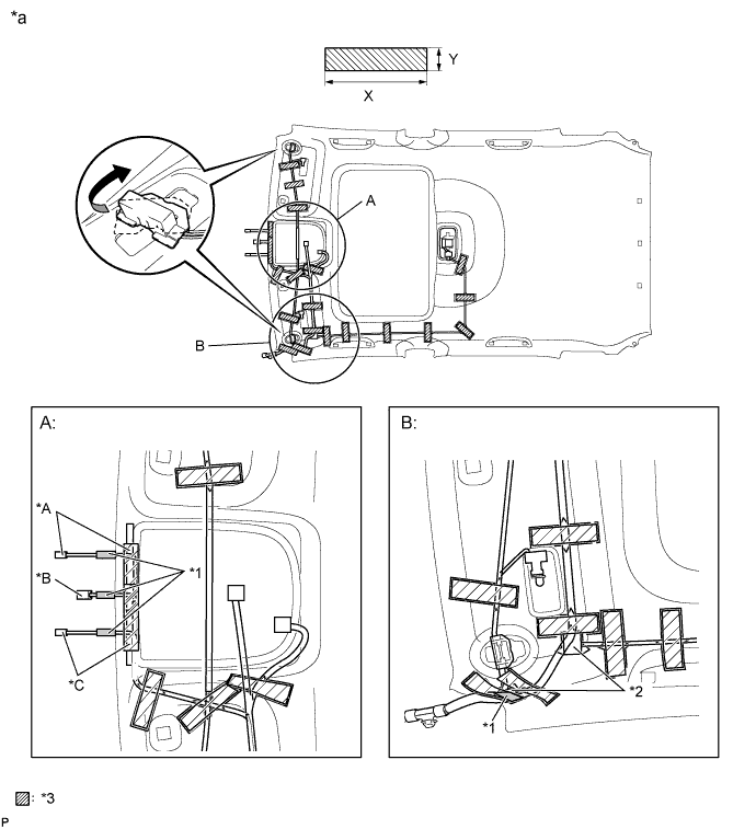
Text in Illustration *A for LHD
w/ Rain Sensor
*B w/ EC Mirror *C for RHD
w/ Rain Sensor
- - *1 No. 1 roof wire marking *2 Joint Box *3 Adhesive Tape - - *a Tape Attachment Locations (Reference) - - Adhesive Tape Size X 80 to 100 mm (3.150 to 3.937 in.) Y 20 mm (0.787 in.) Tech Tips
-
Align the No. 1 roof wire markings in area A in the illustration with the notches of the roof headlining assembly.
-
Align the No. 1 roof wire marking in area B in the illustration with the reference point of the roof headlining assembly.
-
Align the joint boxes with the markings on the roof headlining assembly.
-
-
-
INSTALL NO. 1 ROOF WIRE (w/o Sliding Roof)
-
Temporarily install the No. 1 roof wire aligned with the markings on the roof headlining assembly.
-
Turn the visor connectors clockwise approximately 90° to install the connectors to the roof headlining.
-
Apply adhesive tape to the locations shown in the illustration.
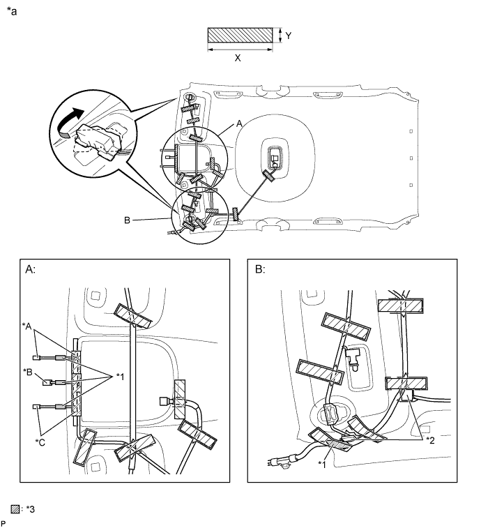
Text in Illustration *A for LHD
w/ Rain Sensor
*B w/ EC Mirror *C for RHD
w/ Rain Sensor
- - *1 No. 1 roof wire marking *2 Joint Box *3 Adhesive Tape - - *a Tape Attachment Locations (Reference) - - Adhesive Tape Size X 80 to 100 mm (3.150 to 3.937 in.) Y 20 mm (0.787 in.) Tech Tips
-
Align the No. 1 roof wire markings in area A in the illustration with the notches of the roof headlining assembly.
-
Align the No. 1 roof wire marking in area B in the illustration with the reference point of the roof headlining assembly.
-
Align the joint boxes with the markings on the roof headlining assembly.
-
-
-
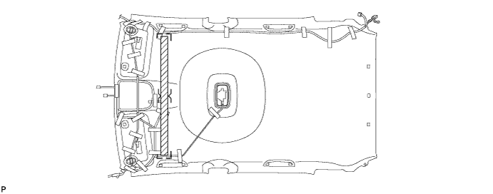
INSTALL NO. 2 ANTENNA CORD SUB-ASSEMBLY
-
Align the No. 2 antenna cord sub-assembly with the markings on the roof headlining assembly and temporarily install the cord.
-
Attach adhesive tape aligned with the markings on the roof headlining assembly as shown in the illustration for removal.
-
Secure the No. 2 antenna cord sub-assembly to the notch of the roof headlining assembly to install the No. 2 antenna cord sub-assembly to the roof headlining assembly.
-
-
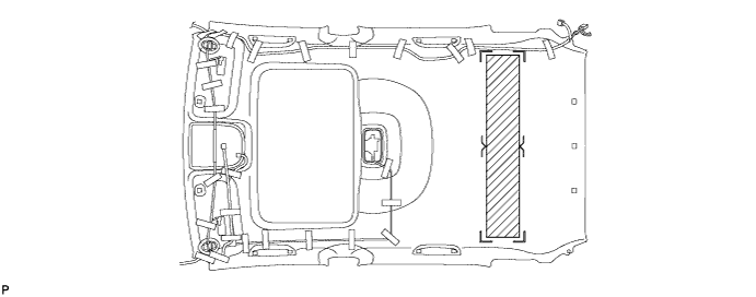
INSTALL NO. 2 ROOF SILENCER PAD (w/o Sliding Roof)
-
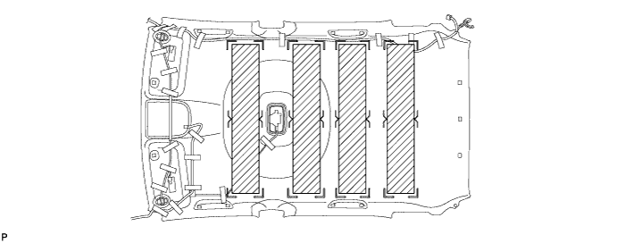
Align the markings on the roof headlining assembly with the No. 2 roof silencer pad and install the silencer pads using hot-melt glue or double-sided tape as shown in the illustration.
-
-
INSTALL NO. 1 ROOF SILENCER PAD (w/ Sliding Roof)
-
Align the markings on the roof headlining assembly with the No. 1 roof silencer pad and install the silencer pad using hot-melt glue or double-sided tape as shown in the illustration.
-
-
INSTALL NO. 1 ROOF SILENCER PAD (w/o Sliding Roof)
-
Align the markings on the roof headlining assembly with the 4 No. 1 roof silencer pads and install the silencer pads using hot-melt glue or double-sided tape as shown in the illustration.
-
-
INSTALL VANITY LIGHT ASSEMBLY
-
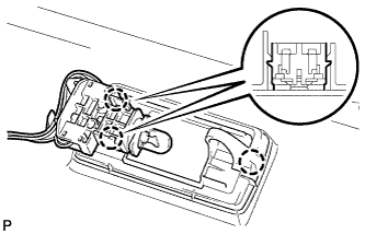
Engage the 3 claws and install the vanity light assembly.
Tech Tips
Use the same procedure for the RH side and the LH side.
-