AIR CONDITIONING UNIT REMOVAL
-
ALIGN FRONT WHEELS FACING STRAIGHT AHEAD
-
REMOVE REAR FLOOR MAT
-
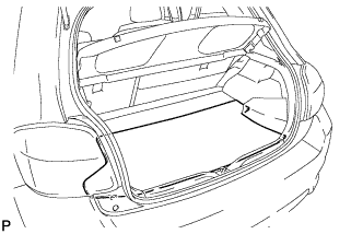
Remove the rear floor mat.
-
-
REMOVE REAR DECK FLOOR BOX
-
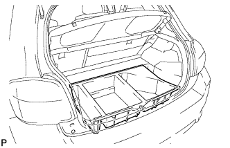
Remove the rear deck floor box.
-
-
REMOVE BATTERY BOX COVER
-
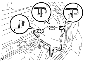
Disengage the 3 guides and remove the battery box cover.
-
-
RECOVER REFRIGERANT FROM REFRIGERATION SYSTEM
-
Turn the A/C switch on.
-
Operate the A/C with the setting temperature at 25°C (77°F) and the blower level at LO for 10 minutes to circulate the refrigerant. This causes most of the compressor oil from the various components of the A/C system to collect in the A/C compressor.
-
Turn the power switch off.
-
Recover the refrigerant from the A/C system using a refrigerant recovery unit.
-
-
DISCONNECT CABLE FROM NEGATIVE BATTERY TERMINAL
CAUTION:
Wait at least 90 seconds after disconnecting the cable from the negative (-) battery terminal to disable the SRS system.
Note
When disconnecting the cable, some systems need to be initialized after the cable is reconnected Click here.
Tech Tips
Before disconnecting the negative battery terminal, set the air conditioning control switch to DEF-MODE.
-
REMOVE FRONT WIPER ARM HEAD CAP
-
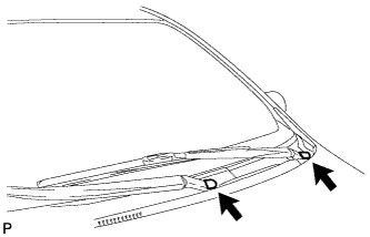
Remove the 2 windshield wiper arm head caps.
-
-
REMOVE FRONT WIPER ARM AND BLADE ASSEMBLY LH
-
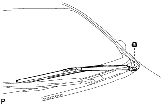
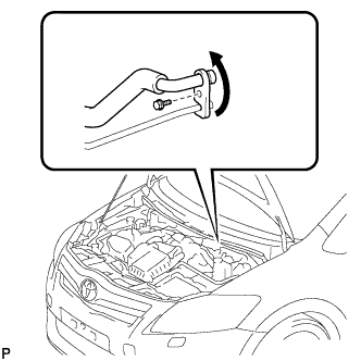
Remove the nut and the front wiper arm and blade assembly LH.
-
-
REMOVE FRONT WIPER ARM AND BLADE ASSEMBLY RH
-
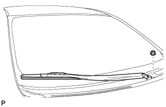
Remove the nut and the front wiper arm and blade assembly RH.
-
-
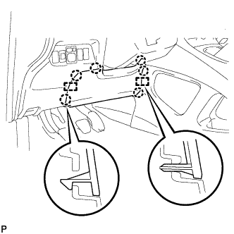
REMOVE HOOD TO COWL TOP SEAL
-
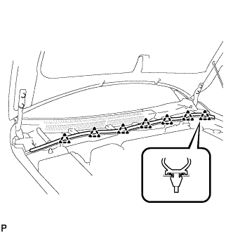
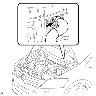
Disengage the 7 clips and remove the hood to cowl top seal.
-
-
REMOVE COWL TOP VENTILATOR LOUVER RH
-
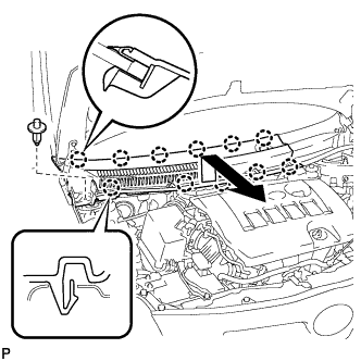
Disengage the clip and 11 claws, and remove the cowl top ventilator louver RH.
-
-
REMOVE COWL TOP VENTILATOR LOUVER LH
-
Disengage the clip and 6 claws, and remove the cowl top ventilator louver LH.
-
-
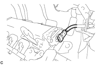
REMOVE WINDSHIELD WIPER MOTOR AND LINK ASSEMBLY
-
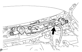
Disconnect the connector.
-
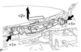
Remove the 2 bolts and the windshield wiper motor and link assembly.
-
-
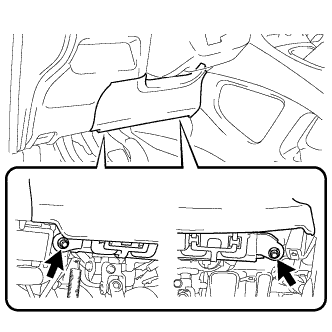
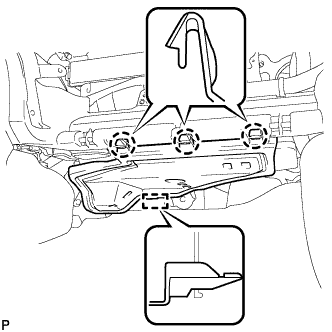
REMOVE COWL BODY MOUNTING REINFORCEMENT LH
-
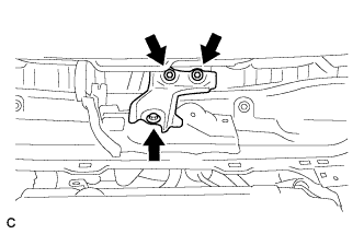
Remove the 3 bolts and cowl body mounting reinforcement LH.
-
-
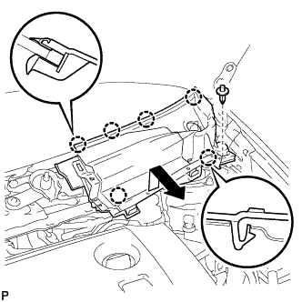
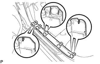
REMOVE OUTER COWL TOP PANEL
-
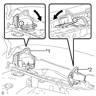
Text in Illustration *1 No. 1 Heater Air Duct Splash Shield Seal *2 Water Guard Plate RH Disengage each claw of the No. 1 heater air duct splash shield seal and water guard plate RH, and bend them.
-
Disengage the clamp and separate the wire harness.
-
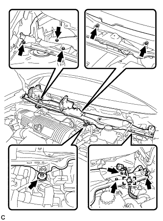
Remove the 8 bolts, nut and outer cowl top panel.
-
-
DISCONNECT SUCTION PIPE SUB-ASSEMBLY
-
Remove the bolt, and slide the hook connector.
-
Disconnect the suction pipe sub-assembly.
-
Remove the O-ring from the suction hose sub-assembly.
Note
Seal the openings of the disconnected parts using vinyl tape to prevent entry of moisture and foreign matter.
-
-
DISCONNECT AIR CONDITIONING TUBE ASSEMBLY
-
Disconnect the air conditioning tube assembly.
-
Remove the O-ring from the air conditioning tube assembly.
Note
Seal the openings of the disconnected parts using vinyl tape to prevent entry of moisture and foreign matter.
-
-
DISCONNECT HEATER OUTLET WATER HOSE
-
Using pliers, grip the claws of the clip, slide the clip and disconnect the heater outlet water hose.
Note
-
Do not apply excessive force to the heater outlet water hose.
-
Prepare a drain pan or cloth in case the coolant leaks.
-
-
-
DISCONNECT HEATER INLET WATER HOSE
Tech Tips
Disconnection procedure for the heater inlet water hose is the same as that for the heater outlet water hose.
-
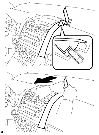
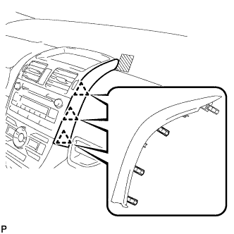
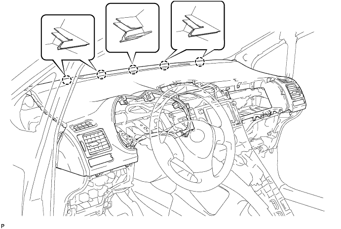
REMOVE INSTRUMENT CLUSTER FINISH PANEL ASSEMBLY
-
Operate the tilt lever to lower the steering wheel assembly.
-
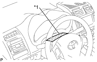
Text in Illustration *1 Protective Tape Apply protective tape to the area shown in the illustration.
-
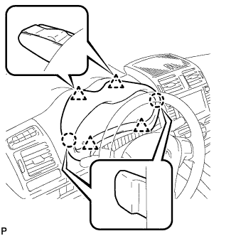
Disengage the 2 claws and 4 clips, and then remove the instrument cluster finish panel assembly.
-
-
REMOVE COMBINATION METER ASSEMBLY
-
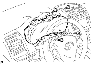
Remove the 4 screws.
-
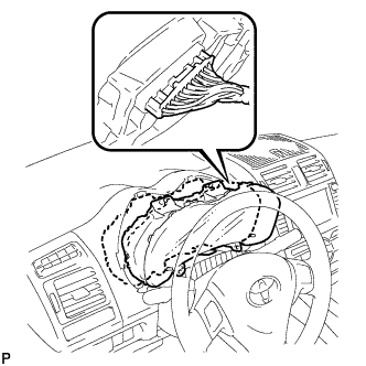
Pull the combination meter assembly, disconnect the connector, and remove the combination meter assembly.
Note
When removing the combination meter assembly, do not damage the upper instrument panel sub-assembly or combination meter assembly.
-
-
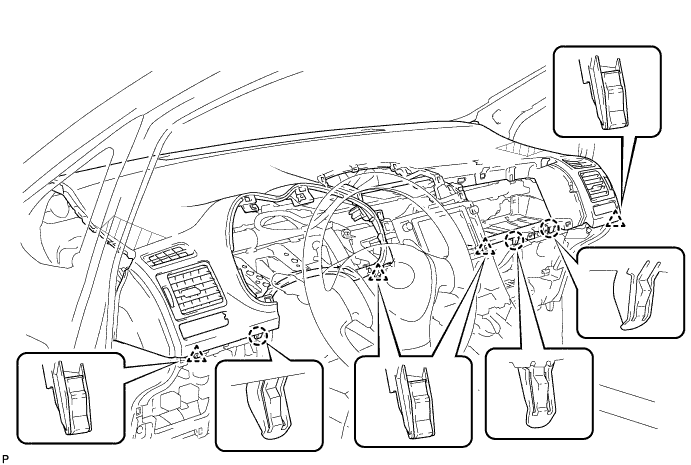
REMOVE INSTRUMENT PANEL FINISH PANEL END LH
-
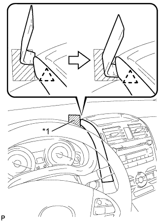
Text in Illustration *1 Protective Tape Apply protective tape to the area shown in the illustration.
-
Insert a roof moulding remover and slide the remover toward the clip.
-
Pull the remover with both hands to disengage the clip as shown in the illustration.
-
Disengage the 3 clips and remove the instrument panel finish panel end LH.
-
-
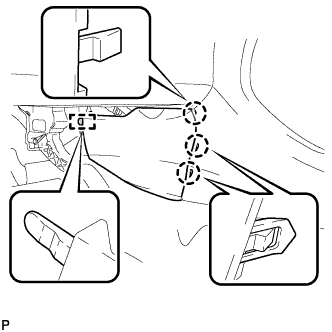
REMOVE INSTRUMENT PANEL FINISH PANEL END RH
-
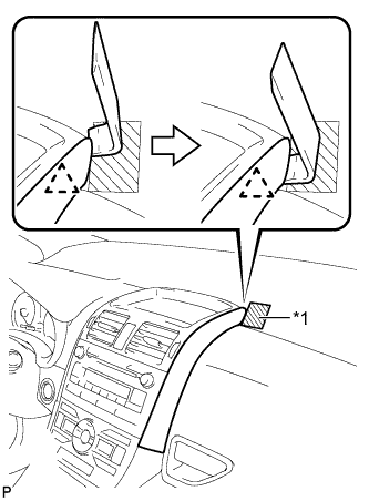
Text in Illustration *1 Protective Tape Apply protective tape to the area shown in the illustration.
-
Insert a roof moulding remover and slide the remover toward the clip.
-
Pull the remover with both hands to disengage the clip as shown in the illustration.
-
Disengage the 3 clips and remove the instrument panel finish panel end RH.
-
-
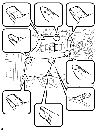
REMOVE CENTER INSTRUMENT PANEL REGISTER ASSEMBLY
-
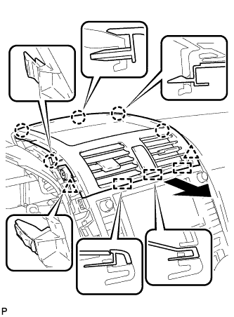
Disengage the 5 claws, 2 clips, and 3 guides.
-
Disconnect the connector and remove the center instrument panel register assembly.
-
-
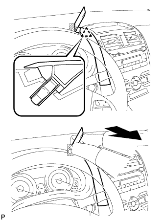
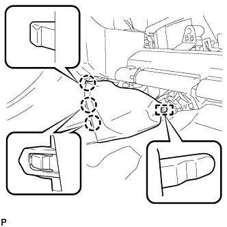
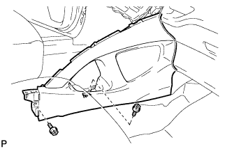
REMOVE FRONT PILLAR GARNISH CORNER PIECE LH
-
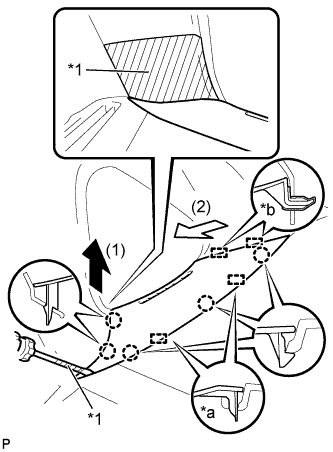
Text in Illustration *1 Protective Tape *a Guide (A) *b Guide (B) Apply protective tape to the areas shown in the illustration.
-
Using a screwdriver, disengage the 5 claws and 2 guides (A).
Tech Tips
Tape the screwdriver tip before use.
-
Disengage the 2 guides (B) and remove the front pillar garnish corner piece LH.
-
-
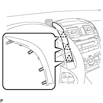
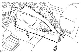
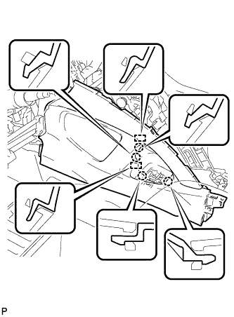
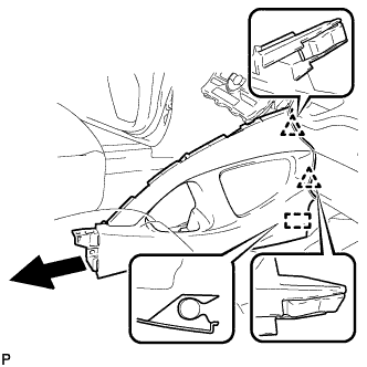
REMOVE FRONT PILLAR GARNISH LH
-
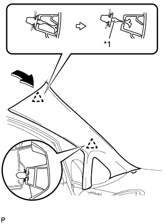
Text in Illustration *1 Front Pillar Garnish Clip Pull the upper part of the garnish toward the inside of the cabin and disengage the garnish from the base of the 2 clips.
Tech Tips
Make the front pillar garnish LH hang down from the front pillar garnish clip.
-
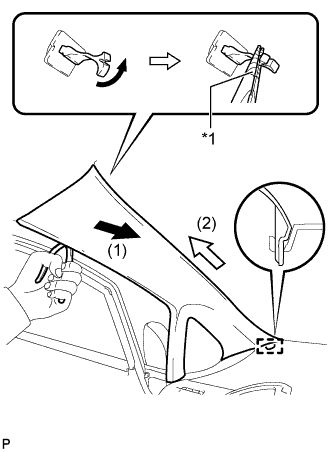
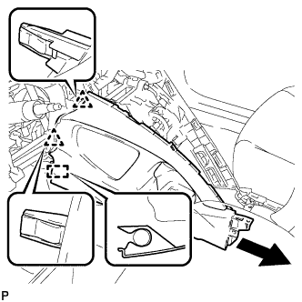
Text in Illustration *1 Protective Tape Turn the end of the front pillar garnish clip 90° with needle-nosed pliers and remove it from the front pillar garnish LH.
Note
-
Front pillar garnish clips are reusable if they are not removed from the vehicle and have no damage.
-
Replace the front pillar garnish clips with new ones if they are removed from the vehicle.
Tech Tips
Tape the tips of the needle-nosed pliers before use.
-
-
Disengage the guide at the front end of the front pillar garnish LH and remove it.
-
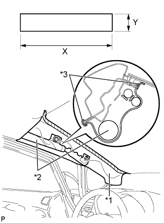
Text in Illustration *1 Protective Cover *2 Curtain Shield Airbag Assembly *3 Adhesive Tape Protect the curtain shield airbag assembly.
Protective Cover Size X 700 mm (27.56 in.) Y 120 mm (4.72 in.)
-
Cover the airbag with a 700 mm (27.56 in.) x 120 mm (4.72 in.) cloth or piece of nylon and fix the ends of the cover with tape as shown in the illustration.
Note
Cover the curtain shield airbag with a protective cover as soon as the front pillar garnish is removed.
-
-
-
REMOVE FRONT PILLAR GARNISH CORNER PIECE RH
Tech Tips
Use the same procedure as for the LH side.
-
REMOVE FRONT PILLAR GARNISH RH
Tech Tips
Use the same procedure as for the LH side.
-
REMOVE REAR CONSOLE BOX COVER
-
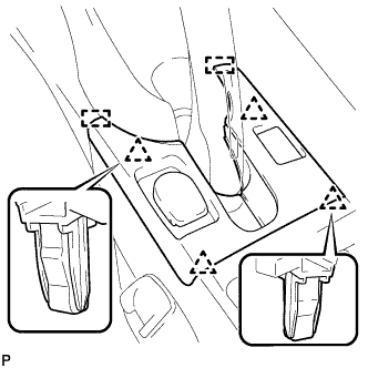
Disengage the 4 clips.
-
Disengage the 2 guides.
-
Disconnect the connector and remove the rear console box cover.
-
-
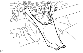
REMOVE UPPER CONSOLE PANEL
-
Disengage the 7 claws.
-
Disconnect the connector and remove the upper console panel.
-
-
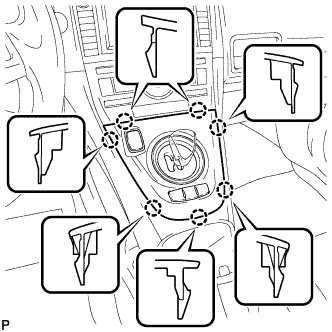
REMOVE LOWER CENTER INSTRUMENT PANEL FINISH PANEL
-
Remove the 2 screws <E> or <F>.
-
Disengage the 4 claws and 6 clips, and remove the lower center instrument panel finish panel.
-
-
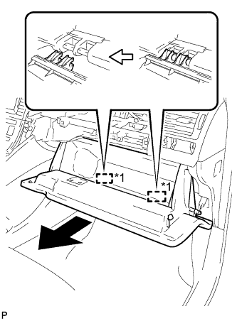
REMOVE GLOVE COMPARTMENT DOOR ASSEMBLY
-
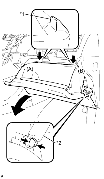
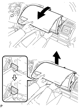
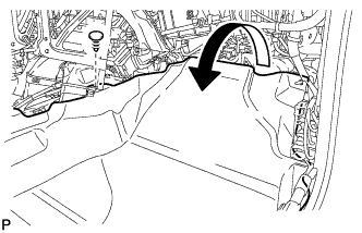
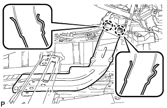
Text in Illustration *1 Stopper *2 Glove Compartment Door Stopper Disengage the claw and release the glove compartment door stopper.
-
Bend portions (A) and (B) in the direction indicated by the arrows in the illustration to release the 2 stoppers, and lower the glove compartment door assembly until the front of the door is level.
-
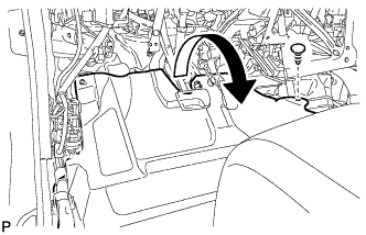
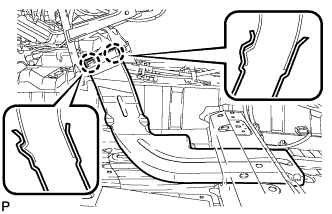
Text in Illustration *1 Hinge Pull the glove compartment door assembly horizontally toward the rear of the vehicle to release the 2 hinges, and remove the glove compartment door assembly.
Note
Pulling the glove compartment door assembly upward to remove it will cause the hinges to deform when reinstalling the door. Be sure to pull out the compartment door horizontally.
-
-
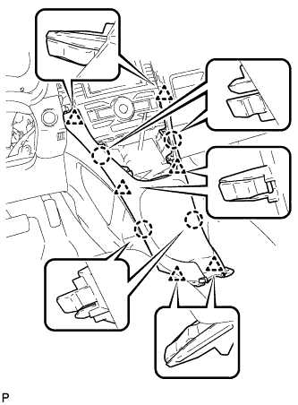
REMOVE NO. 1 INSTRUMENT PANEL BOX DOOR SUB-ASSEMBLY
-
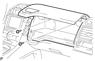
Remove the 2 screws <C> or <D>.
-
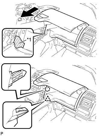
Text in Illustration *1 Protective Tape Apply protective tape to the area shown in the illustration.
-
Disengage the claw and clip.
-
Disengage the 2 claws and 2 clips.
-
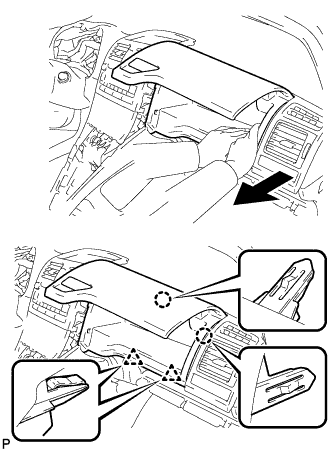
As shown in the illustration, remove the No. 1 instrument panel box door sub-assembly.
-
w/ USB Audio System:
-
Disengage the clamp and disconnect the connector.
-
-
-
DISCONNECT INSTRUMENT PANEL WIRE ASSEMBLY
-
Check that the power switch is off.
-
Check that the cable is disconnected from the negative (-) battery terminal.
CAUTION:
Wait at least 90 seconds after disconnecting the cable from the negative (-) battery terminal to disable the SRS system.
-
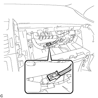
Disconnect the connector.
Note
When disconnecting any airbag connector, take care not to damage the airbag wire harness.
-
-
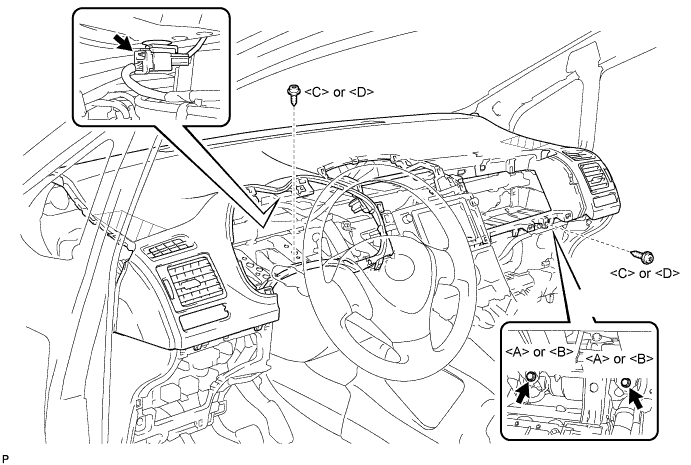
REMOVE UPPER INSTRUMENT PANEL SUB-ASSEMBLY
-
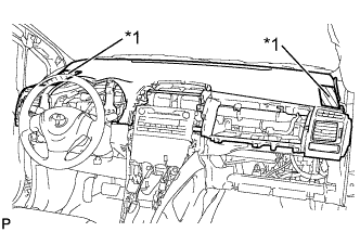
Text in Illustration *1 Protective Tape Apply protective tape to the areas shown in the illustration.
-
Operate the tilt lever to lower the steering wheel assembly.
-
Disconnect the connector.
-
Remove the 2 screws <C> or <D>.
-
Remove the 2 passenger airbag bolts <A> or <B>.
-
Disengage the 4 clips and 3 claws.
-
Disengage the 5 claws and remove the upper instrument panel sub-assembly.
Note
When removing the upper instrument panel sub-assembly, be careful not to damage it or the steering wheel assembly.
-
-
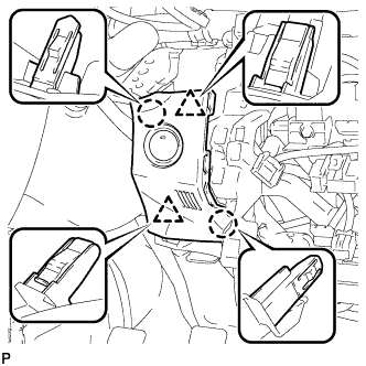
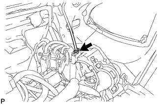
REMOVE POWER STEERING ECU ASSEMBLY
-
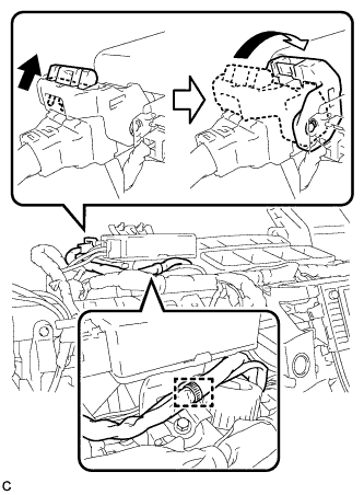
Separate the wire harness clamp from the power steering ECU assembly.
-
Disconnect the connector from the power steering ECU assembly.
Tech Tips
As shown in the illustration, pull out the lock of the lock lever and turn the lock lever to disconnect the connector.
-
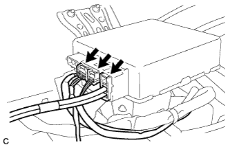
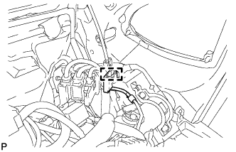
Disconnect the 3 connectors from the power steering ECU assembly.
-
Remove the bolt, 2 nuts, and the power steering ECU assembly.
-
-
REMOVE NO. 1 INSTRUMENT PANEL UNDER COVER SUB-ASSEMBLY
-
Remove the 2 screws <C> or <D>.
-
Disengage the claw and guide, and remove the No. 1 instrument panel under cover sub-assembly.
-
-
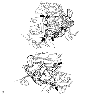
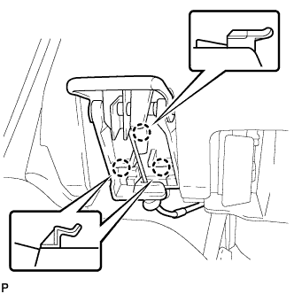
REMOVE DRIVER SIDE KNEE AIRBAG ASSEMBLY
CAUTION:
When storing the driver side knee airbag assembly, keep the airbag deployment side facing upward.
-
Check that the power switch is off.
-
Check that the cable is disconnected from the negative (-) battery terminal.
CAUTION:
Wait at least 90 seconds after disconnecting the cable from the negative (-) battery terminal to disable the SRS system.
-
Remove the 2 bolts (upper side).
-
Remove the 2 bolts (lower side).
-
Disengage the 6 claws and 2 guides.
-
Disconnect the connector to remove the driver side knee airbag assembly.
Note
When disconnecting any airbag connector, take care not to damage the airbag wire harness.
-
-
REMOVE STEERING POST ASSEMBLY
-
REMOVE CENTER INSTRUMENT CLUSTER FINISH PANEL SUB-ASSEMBLY (w/o Radio Receiver)
-
Disengage the 4 clips and remove the center instrument cluster finish panel sub-assembly.
-
-
REMOVE RADIO RECEIVER OPENING COVER WITH BRACKET (w/o Radio Receiver)
-
Remove the 4 bolts <K> and remove the radio receiver opening cover with bracket.
-
-
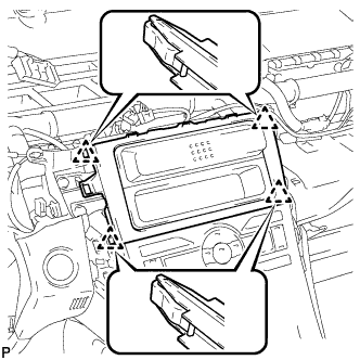
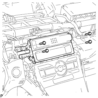
REMOVE RADIO RECEIVER WITH BRACKET (w/ Radio Receiver)
-
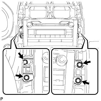
Remove the 4 bolts.
-
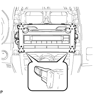
Pull the radio receiver with bracket toward the rear of the vehicle and disengage the 4 clips.
-
Disconnect each connector and remove the radio receiver with bracket.
-
-
REMOVE NAVIGATION RECEIVER WITH BRACKET (w/ Navigation System)
-
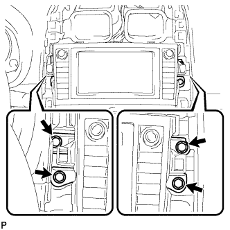
Remove the 4 bolts.
-
Pull the navigation receiver with bracket toward the rear of the vehicle and disengage the 4 clips.
-
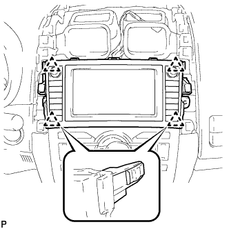
Disconnect each connector and remove the navigation receiver with bracket.
-
-
REMOVE AIR CONDITIONING CONTROL ASSEMBLY
-
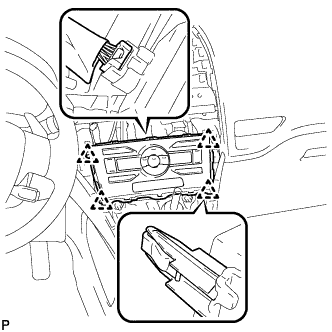
Disengage the 4 clips and remove the air conditioning control assembly.
-
Disconnect the connector.
-
-
REMOVE CONSOLE BOX CARPET
-
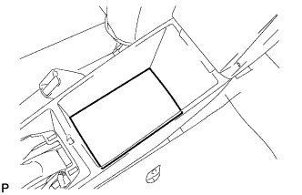
Remove the console box carpet.
-
-
REMOVE REAR CONSOLE BOX ASSEMBLY
-
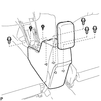
Remove the 4 bolts and 2 screws.
-

Disengage the 4 claws and remove the rear console box assembly.
-
-
REMOVE FRONT DOOR SCUFF PLATE LH
-
Disengage the 10 claws and remove the front door scuff plate LH.
-
-
REMOVE COWL SIDE TRIM BOARD LH
-

Disengage the 2 clips.
-
Disengage the guide and remove the cowl side trim board LH.
-
-
REMOVE FRONT DOOR SCUFF PLATE RH
Tech Tips
Use the same procedure as for the LH side.
-
REMOVE COWL SIDE TRIM BOARD RH
Tech Tips
Use the same procedure as for the LH side.
-
REMOVE NO. 2 INSTRUMENT PANEL UNDER COVER SUB-ASSEMBLY
-
Disengage the 3 claws.
-
Disengage the guide and remove the No. 2 instrument panel under cover sub-assembly.
-
-
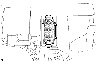
REMOVE FUSE BOX OPENING COVER
-
Disengage the 4 claws and 4 clips.
-
Disconnect each connector and then remove the fuse box opening cover.
-
-
REMOVE FRONT NO. 1 CONSOLE BOX INSERT
-
Disengage the 3 claws.
-
Disengage the guide and remove the front No. 1 console box insert.
-
-
REMOVE FRONT NO. 2 CONSOLE BOX INSERT
-
Disengage the 3 claws.
-
Disengage the guide and remove the front No. 2 console box insert.
-
-
REMOVE INSTRUMENT PANEL UNDER TRAY
-

Text in Illustration *1 Protective Tape Using a screwdriver, disengage the 4 claws and remove the instrument panel under tray.
Tech Tips
Tape the screwdriver tip before use.
-
-
REMOVE LOWER NO. 1 INSTRUMENT PANEL FINISH PANEL
-
Remove the 2 screws <E> or <F>.
-
Disengage the 4 claws and 2 guides.
-
Disengage the 2 clips and guide, and remove the lower No. 1 instrument panel finish panel.
-
-
REMOVE LOWER NO. 2 INSTRUMENT PANEL FINISH PANEL
-
Remove the 2 screws <E> or <F>.
-
Disengage the 2 clips and guide, and remove the lower No. 2 instrument panel finish panel.
-
-
REMOVE NO. 1 SWITCH HOLE BASE
-
Disengage the 2 claws and 2 clips.
-
Disconnect the connectors and remove the No. 1 switch hole base.
-
-
DISCONNECT TRANSMISSION INSTRUMENT PANEL SHIFT ASSEMBLY
-
Disconnect the connector and wire harness clamp from the transmission instrument panel shift assembly.
-
Remove the 4 nuts and transmission instrument panel shift assembly.
-
-
REMOVE ANTENNA CORD SUB-ASSEMBLY (for LHD)
-
Disconnect the connector.
-
Disengage the clamp.
-
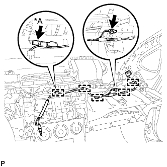
Text in Illustration *A w/o Radio Receiver Remove the bolt.
-
w/o Radio Receiver:
-
Disconnect the connector.
-
-
Disengage the 5 clamps and remove the antenna cord sub-assembly.
-
-
REMOVE ANTENNA CORD SUB-ASSEMBLY (for RHD)
-
Disconnect the connector.
-
Disengage the clamp.
-
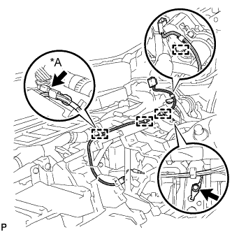
Text in Illustration *A w/o Radio Receiver Remove the bolt.
-
w/o Radio Receiver:
-
Disconnect the connector.
-
-
Disengage the 4 clamps and remove the antenna cord sub-assembly.
-
-
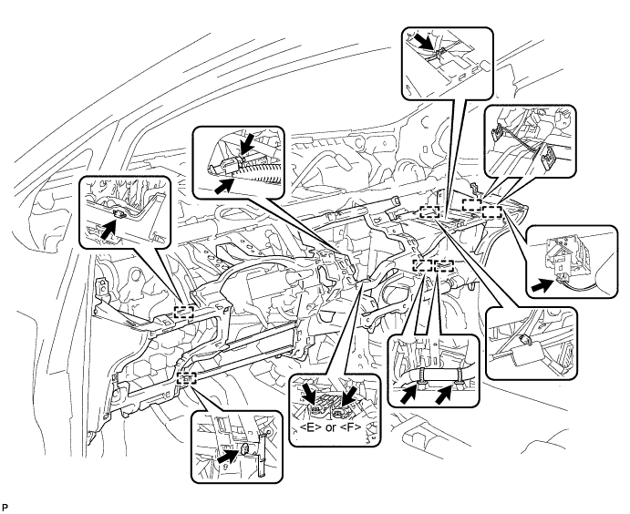
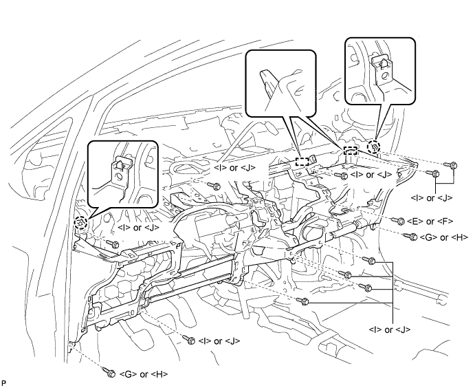
REMOVE LOWER INSTRUMENT PANEL SUB-ASSEMBLY
-
Disengage the 2 claws and DLC3.
-
Disengage the 3 claws and the hood lock control cable assembly.
-
Disengage each clamp.
-
Disconnect each connector.
-
Remove the 2 screws <E> or <F>.
-
Remove the screw <E> or <F>.
-
Remove the 2 bolts <G> or <H>.
-
Remove the 10 screws <I> or <J>.
-
Disengage the 2 claws and 2 guides, and remove the lower instrument panel sub-assembly.
-
-
REMOVE REAR NO. 3 AIR DUCT (for Cold Area)
-
Remove the clip.
-
Turn back the floor carpet.
-
Disengage the 2 claws and remove the rear No. 3 air duct.
-
-
REMOVE REAR NO. 1 AIR DUCT (for Cold Area)
-
Remove the clip.
-
Turn back the floor carpet.
-
Disengage the 2 claws and remove the rear No. 1 air duct.
-
-
REMOVE NO. 1 AIR DUCT SUB-ASSEMBLY
-
Remove the 2 nuts and the No. 1 air duct sub-assembly.
-
-
REMOVE LOWER DEFROSTER NOZZLE ASSEMBLY
-
Disengage the 6 claws and remove the lower defroster nozzle assembly.
-
-
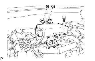
REMOVE CENTER INSTRUMENT PANEL TO COWL BRACE
-
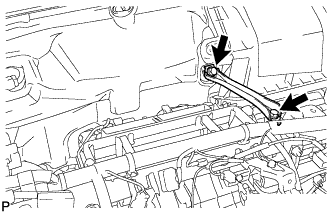
Remove the 2 bolts and the center instrument panel to cowl brace.
-
-
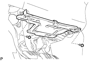
REMOVE INSTRUMENT PANEL BRACE ASSEMBLY
-
Disengage each clamp.
-
Remove the 2 screws.
-
Remove the 2 bolts, the 2 nuts, and the instrument panel brace assembly.
-
-
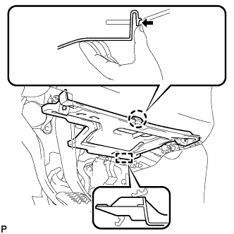
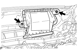
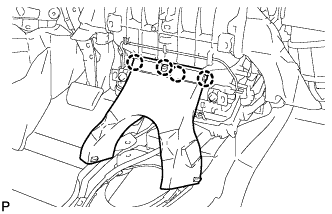
REMOVE HEATER COVER (except Cold Area)
-
Disengage the 4 claws and remove the heater cover.
-
-
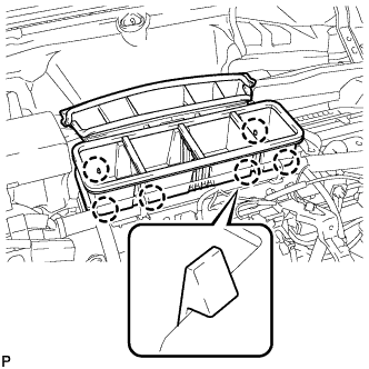
REMOVE REAR NO. 2 AIR DUCT (for Cold Area)
-
Disengage the 4 claws and remove the rear No. 2 air duct.
-
-
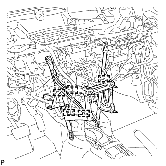
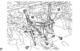
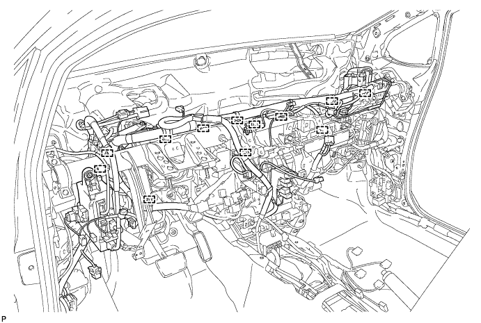
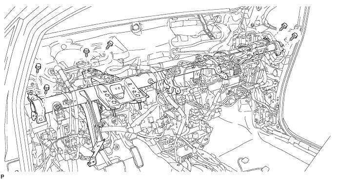
REMOVE INSTRUMENT PANEL REINFORCEMENT ASSEMBLY
-
Disengage each clamp and the wire harness.
-
Disconnect each connector.
-
Disengage each clamp.
-
Remove the 13 bolts and disengage the wire harness and junction block.
-
Disengage the cooler drain hose.
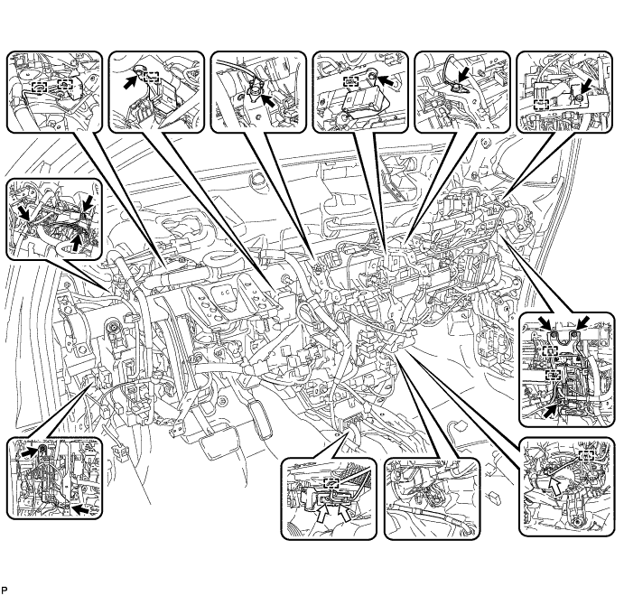
-
Remove the 6 bolts.
-
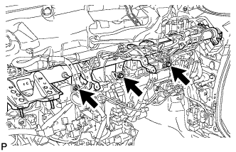
Remove the 3 bolts and the instrument panel reinforcement assembly.
-
-
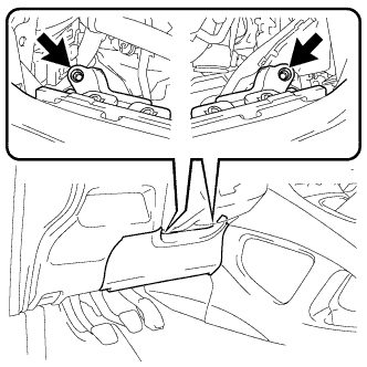
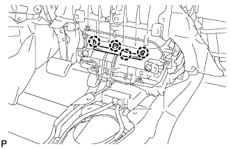
REMOVE AIR CONDITIONING UNIT
-
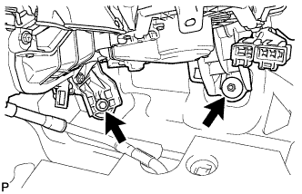
Remove the bolt, the nut, and the air conditioning unit.
Note
-
Be sure to support the air conditioning unit assembly when removing it because failure to do so may cause the bracket of the air conditioning unit assembly to break.
-
When disassembling the air conditioning unit, eliminate static electricity by touching the vehicle body to prevent the components from being damaged.
-
-