AIR CONDITIONING SYSTEM, Diagnostic DTC:B1473/73
| DTC Code | DTC Name |
|---|---|
| B1473/73 | A/C Inverter Start-up Signal System Malfunction |
DESCRIPTION
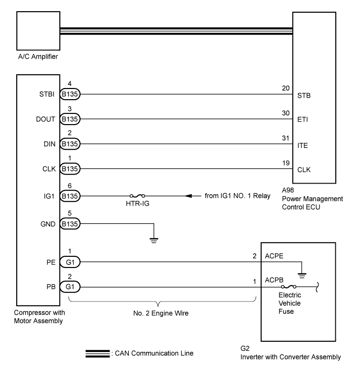
The inverter activation signal is sent to the compressor with motor assembly from the power management control ECU. Compressor control is stopped and the DTC is stored if there is an open or short in the signal circuit.
| DTC No. | DTC Detection Condition | Trouble Area |
|---|---|---|
| B1473/73 | Open or short in A/C inverter start-up signal system. |
|
WIRING DIAGRAM
INSPECTION PROCEDURE
CAUTION:
-
Wear electrically insulated gloves and pull out the service plug grip before inspection as procedures may require disconnecting high-voltage connectors. Be sure to carry the removed service plug grip because other workers may install it by mistake.
-
Do not touch the high-voltage connectors or terminals for 10 minutes after the service plug grip is removed.
Note
The hybrid control system and air conditioning system output DTCs separately. Inspect DTCs following the flow chart for the hybrid control system first if any DTCs from those systems are output simultaneously.
PROCEDURE
-
CHECK CAN COMMUNICATION SYSTEM
-
Using the intelligent tester, check if the CAN communication system is functioning normally.
Result Result Proceed to CAN DTC is not output A CAN DTC is output B
B 
GO TO CAN COMMUNICATION SYSTEM Click here
A 
-
-
CHECK DIAGNOSTIC TROUBLE CODE
-
Check if DTCs for the air conditioning system and the hybrid control system are output using the intelligent tester.
Result Result Proceed to Only DTC B1473 is output A DTCs B1473 and P3108 are output simultaneously (B1498 is not output) DTCs B1473 and B1498 are output simultaneously (P3108 is not output) B DTCs B1473, B1498 and P3108 are output simultaneously DTCs other than P3108 are output for hybrid control system C
B
GO TO DTC B1498/98 Click here
C
GO TO HYBRID CONTROL SYSTEM Click here
A
-
-
CHECK HARNESS AND CONNECTOR (POWER MANAGEMENT CONTROL ECU - COMPRESSOR WITH MOTOR)
CAUTION:
Do not disconnect the connector on the high-voltage side.
-
Disconnect the A98 connector from the power management control ECU.
-
Disconnect the B135 connector from the compressor with motor assembly.
-
Measure the resistance according to the value(s) in the table below.
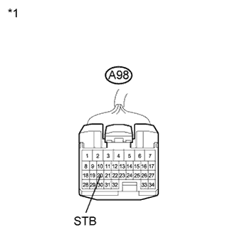
Standard Resistance Tester Connection Condition Specified Condition A98-20 (STB) - B135-4 (STBI) Always Below 1 Ω A98-20 (STB) - Body ground Always 10 kΩ or higher Text in Illustration *1 Front view of wire harness connector
(to Power Management Control ECU)
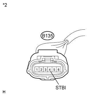
*2 Front view of wire harness connector
(to Compressor with Motor Assembly)
NG
REPAIR OR REPLACE HARNESS OR CONNECTOR
OK
-
-
INSPECT COMPRESSOR WITH MOTOR ASSEMBLY
-
Reconnect the B135 connector to the compressor with motor assembly.
-
Text in Illustration *1 Front view of wire harness connector
(to Power Management Control ECU)
Measure the voltage according to the value(s) in the table below.
Standard Voltage Tester Connection Condition Specified Condition A98-20 (STB) - Body ground Power switch on (IG) 11 to 14 V A98-20 (STB) - Body ground Power switch off Below 1 V
NG
REPLACE COMPRESSOR WITH MOTOR ASSEMBLY Click here
OK 
REPLACE POWER MANAGEMENT CONTROL ECU Click here
-