CENTER AIRBAG SENSOR ASSEMBLY INSTALLATION

-
INSTALL CENTER AIRBAG SENSOR ASSEMBLY
-
Check that the power switch is off.
-
Check that the cable is disconnected from the negative (-) battery terminal.
CAUTION:
Wait at least 90 seconds after disconnecting the cable from the negative (-) battery terminal to disable the SRS system.
-
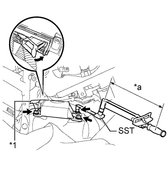
Text in Illustration *1 Waterproof Sheet *a Fulcrum Length Using SST and a torque wrench, install the center airbag sensor assembly with the 3 bolts.
- SST
- 09961-00950
- Torque:
- without SST
- 18 N*m { 178 kgf*cm, 13 ft.*lbf }
- with SST
- 11 N*m { 112 kgf*cm, 8 ft.*lbf }
Note
-
Use a torque wrench with a fulcrum length of 250 mm (9.84 in.).
-
This torque value is effective when SST is parallel to a torque wrench.
-
If the center airbag sensor assembly has been dropped, or there are any cracks, dents or other defects in the case or connector, replace it with a new one.
-
When installing the center airbag sensor assembly, be careful that the SRS wiring does not interfere with or is not pinched between other parts.
-
When the power switch is first turned on (IG) after the center airbag sensor assembly has been replaced, make sure that no one is in the vehicle.
-
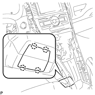
Connect the connectors to the center airbag sensor assembly as shown in the illustration.
Note
When connecting any airbag connector, take care not to damage the airbag wire harness.
-
Check that the waterproof sheet is properly set.
-
Check that there is no looseness in the installation parts of the center airbag sensor assembly.
-
-
INSTALL LOWER NO. 2 INSTRUMENT PANEL FINISH PANEL
-
Engage the 2 clips and guide.
-
Install the lower No. 2 instrument panel finish panel with the 2 screws <E> or <F>.
-
-
INSTALL LOWER NO. 1 INSTRUMENT PANEL FINISH PANEL
-
Engage the 2 clips and guide.
-
Engage the 4 claws and 2 guides.
-
Install the lower No. 1 instrument panel finish panel with the 2 screws <E> or <F>.
-
-
INSTALL INSTRUMENT PANEL UNDER TRAY
-
Engage the 4 claws and install the instrument panel under tray.
-
-
INSTALL FRONT NO. 1 CONSOLE BOX INSERT
-
Engage the guide.
-
Engage the 3 claws and install the front No. 1 console box insert.
-
-
INSTALL FRONT NO. 2 CONSOLE BOX INSERT
-
Engage the guide.
-
Engage the 3 claws and install the front No. 2 console box insert.
-
-
INSTALL REAR CONSOLE BOX ASSEMBLY
-
Engage the 4 claws.
-
Install the rear console box assembly with the 4 bolts and 2 screws.
-
-
INSTALL CONSOLE BOX CARPET
-
Install the console box carpet.
-
-
INSTALL LOWER CENTER INSTRUMENT PANEL FINISH PANEL
-
Engage the 4 claws and 6 clips.
-
Install the lower center instrument panel finish panel with the 2 screws <E> or <F>.
-
-
INSTALL UPPER CONSOLE PANEL
-
Engage the 7 claws and install the upper console panel.
-
-
INSTALL REAR CONSOLE BOX COVER
-
Connect the connector.
-
Engage the 2 guides and 4 clips to install the rear console box cover.
-
-
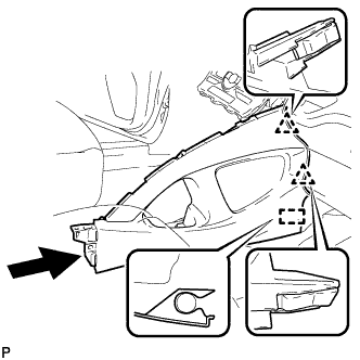
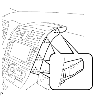
INSTALL INSTRUMENT PANEL FINISH PANEL END LH
-
Engage the 4 clips and install the instrument panel finish panel end LH.
-
-
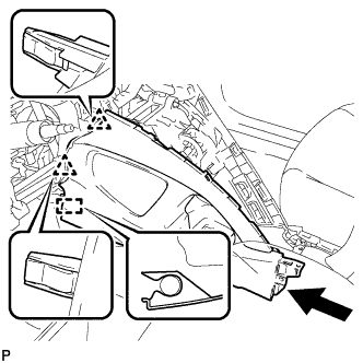
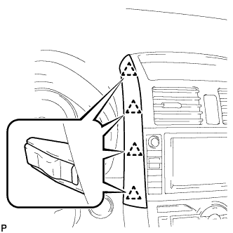
INSTALL INSTRUMENT PANEL FINISH PANEL END RH
-
Engage the 4 clips and install the instrument panel finish panel end RH.
-
-
CONNECT CABLE TO NEGATIVE BATTERY TERMINAL
Note
When disconnecting the cable, some systems need to be initialized after the cable is reconnected Click here.
-
INSTALL BATTERY BOX COVER
-
Engage the 3 guides to install the battery box cover.
-
-
INSTALL REAR DECK FLOOR BOX
-
Install the rear deck floor box.
-
-
INSTALL REAR FLOOR MAT
-
Install the rear floor mat.
-
-
PERFORM DIAGNOSTIC SYSTEM CHECK
-
INSPECT SRS WARNING LIGHT