METER / GAUGE SYSTEM Engine Coolant Temperature Receiver Gauge Malfunction
DESCRIPTION
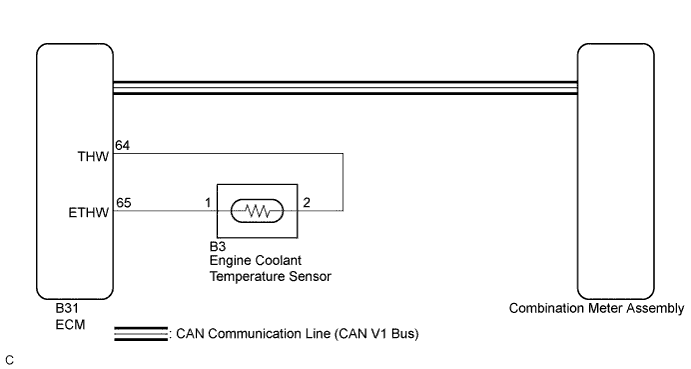
In this circuit, the meter ECU receives engine coolant temperature signals from the ECM using the CAN communication system (CAN V1 Bus). The meter ECU displays engine coolant temperature that is calculated based on the data received from the ECM.
WIRING DIAGRAM
INSPECTION PROCEDURE
Tech Tips
-
If there is an open or short in the engine coolant temperature sensor circuit, the ECM stores the DTCs. Troubleshoot the SFI System Click here.
-
If the exhaust heat recirculation system has a malfunction, the 9th bar of the engine coolant temperature receiver gauge blinks to inform the driver of the malfunction.
PROCEDURE
-
CHECK CAN COMMUNICATION SYSTEM
-
Check if a CAN communication DTC is output Click here.
Result Result Proceed to CAN communication DTC is not output. A CAN communication DTC is output. B
B 
GO TO CAN COMMUNICATION SYSTEM Click here
A 
-
-
SYSTEM CHECK
-
Check the engine coolant temperature receiver gauge frame and the engine coolant temperature receiver mark.
Result Result Proceed to The engine coolant temperature receiver gauge frame and the engine coolant temperature receiver mark does not come on. A The engine coolant temperature receiver gauge frame and the engine coolant temperature receiver mark comes on. B
B 
CHECK FOR DTC Click here
A
-
-
PERFORM ACTIVE TEST USING INTELLIGENT TESTER (WATER TEMPERATURE METER OPERATION)
-
Connect the intelligent tester to the DLC3.
-
Turn the power switch on (IG).
-
Turn the tester on.
-
Enter the following menus: Body / Combination Meter / Active Test.
-
Check the operation by referring to the table below.
Combination Meter Tester Display Test Part Control Range Diagnostic Note Water Temperature Meter Operation Engine coolant temperature receiver gauge HIGH, 120, 110, NORMAL, 80, 70, 60, LOW - OK Engine coolant temperature receiver gauge indication is normal.
NG
REPLACE COMBINATION METER ASSEMBLY Click here
OK
-
-
CHECK FOR DTC
-
Check for the DTCs.
Result Result Proceed to No DTC is output. A DTC P0115 is output. B DTC B1503 is output. C
B
GO TO SFI SYSTEM Click here
C
GO TO METER / GAUGE SYSTEM Click here
A
-
-
READ VALUE USING INTELLIGENT TESTER (COOLANT TEMPERATURE, COOLANT TEMP)
-
Connect the intelligent tester to the DLC3.
-
Turn the power switch on (IG).
-
Turn the intelligent tester on.
-
Enter the following menus:
-
for Combination Meter: Body / Combination Meter / Data List.
-
for Engine: Powertrain / Engine / Data List.
-
-
Check the values by referring to the table below.
Combination Meter Tester Display Measurement Item/Range Normal Condition Diagnostic Note Coolant Temperature Engine coolant temperature/0 to 140°C (32 to 284°F) After warming up: 80 to 95°C (176 to 203°F)
-
If -60°C (-76°F): Sensor circuit open
-
If 140°C (284°F) or more: Sensor circuit shorted
OK Engine coolant temperature value displayed on the intelligent tester is almost the same as the engine coolant temperature receiver gauge indication. -
-
Record the temperature displayed on the intelligent tester.
-
Check the values by referring to the table below.
Engine Tester Display Measurement Item/Range Normal Condition Diagnostic Note Coolant Temp Engine coolant temperature/Min.: -40°C (-40°F), Max.: 215°C (419°F) After warming up: 80 to 100°C (176 to 212°F)
-
If -40°C (-40°F): sensor circuit open
-
If 140°C (284°F) or more: sensor circuit shorted
OK When the Data List values of the ECUs do not match, a signal output error of the ECM is suspected. -
NG
REPLACE ECM Click here
OK 
REPLACE COMBINATION METER ASSEMBLY Click here
-