METER / GAUGE SYSTEM TERMINALS OF ECU
-
COMBINATION METER ASSEMBLY

-
Measure the voltage and resistance according to the value(s) in the table below.
Terminal No. (Symbol) Wiring Color Terminal Description Condition Specified Condition E46-1 (WRNP) - Body ground BE - Body ground Front passenger seat belt warning light signal Front passenger seat occupied, power switch on (IG), front passenger seat belt warning light OFF 11 to 14 V Front passenger seat occupied, power switch on (IG), front passenger seat belt warning light is blinking Below 1 V ←→ 11 to 14 V E46-5 (B) - Body ground G - Body ground Turn indicator light signal Power switch on (IG), turn signal RH indicator light OFF Below 1 V Power switch on (IG), turn signal RH indicator light blinking Below 1 V ←→ 11 to 14 V E46-6 (B) - Body ground Y - Body ground Turn indicator light signal Power switch on (IG), turn signal LH indicator light OFF Below 1 V Power switch on (IG), turn signal LH indicator light blinking Below 1 V ←→ 11 to 14 V E46-7 (TWS3)*1 - E46-26 (E2)*1 B - G Water temperature signal Power switch on (IG), water temperature is -60°C (-76°F) or less Below 1 V Power switch on (IG), water temperature is 125°C (257°F) or higher 11 to 14 V E46-9 (TX1+) - Body ground G - Body ground Ground (Temperature ground) Always Below 1 Ω E46-10 (E) - Body ground BR - Body ground Ground (Fuel ground) Always Below 1 Ω E46-12 (PKBI) - Body ground L - Body ground Front passenger seat buckle switch signal Power switch on (IG), front passenger seat belt is unfastened Below 1 V Power switch on (IG), front passenger seat belt is fastened 11 to 14 V E46-19 (LVWG)*2 - Body ground GR - Body ground Headlight beam level control indicator light signal Power switch on (IG), LEVELING indicator light OFF 11 to 14 V Power switch on (IG), LEVELING indicator light ON Below 1 V E46-20 (EFI) - Body ground LG - Body ground Check engine warning light signal Power switch on (IG), CHECK ENGINE warning light ON Below 3 V Power switch on (IG), CHECK ENGINE warning light OFF 11 to 14 V E46-21 (SW1) - Body ground R - Body ground Steering pad switch signal Power switch on (IG), DISP switch pressed Below 1 V Power switch on (IG), DISP switch not pressed 11 to 14 V E46-23 (TEMP) - Body ground W - Body ground Outside temperature signal Power switch on (IG), outside temperature 25°C (77°F) Approx. 1.3 V E46-25 (L) - Body ground Y - Body ground Fuel signal Power switch on (IG), fuel level is FULL Below 1 V Power switch on (IG), fuel level is EMPTY 3 to 7 V E46-26 (E2)*1 - Body ground G - Body ground Ground (Water temperature ground) Always Below 1 Ω E46-27 (CANH) - E46-28 (CANL) G - W CAN communication signal - - E46-30 (ET) - Body ground BR - Body ground Ground (Signal ground) Always Below 1 Ω E46-32 (B) - Body ground W - Body ground Battery Always 11 to 14 V E46-33 (IG+) - Body ground P - Body ground Power switch signal Power switch off Below 1 V Power switch on (IG) 11 to 14 V E46-35 (SI) - Body ground V - Body ground Speed signal for other systems (Input) Power switch on (IG), wheel turned slowly Pulse generation (See waveform 1) E46-36 (+S) - Body ground V - Body ground Speed signal for other systems (Output) Wheel turned slowly Pulse generation (See waveform 1) E46-38 (S) - Body ground V - Body ground Engine oil pressure warning light signal Power switch on (IG), engine oil pressure warning message not displayed 11 to 14 V Power switch on (IG), engine oil pressure warning message displayed Below 1 V
-
*1: w/ Exhaust Heat Recirculation System
-
*2: w/ Automatic Type Headlight Beam Level Control
Tech Tips
Vehicle speed signal that has been received and transmitted via the direct line is used for another system, and is not used for combination meter operation.
-
-
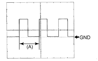
Waveform 1 (Reference): Using an oscilloscope:
Item Condition Tool setting 5 V/DIV., 20 ms./DIV. Vehicle condition Wheel being rotated Tech Tips
When the system is functioning normally, one wheel revolution generates 4 pulses. As the vehicle speed increases, the width indicated by (A) in the illustration narrows.
-
-
COMBINATION METER ASSEMBLY INNER CIRCUIT
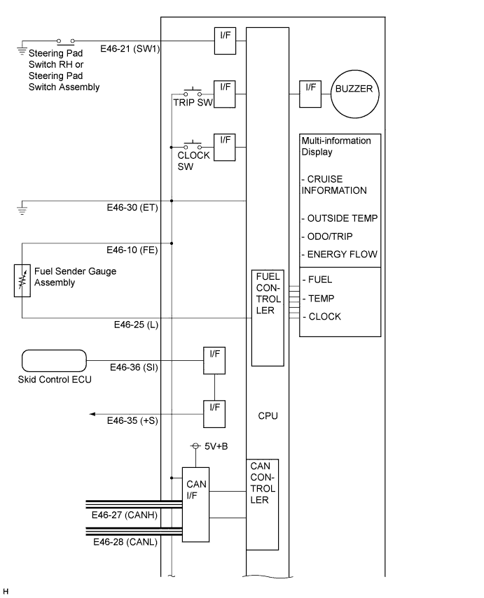
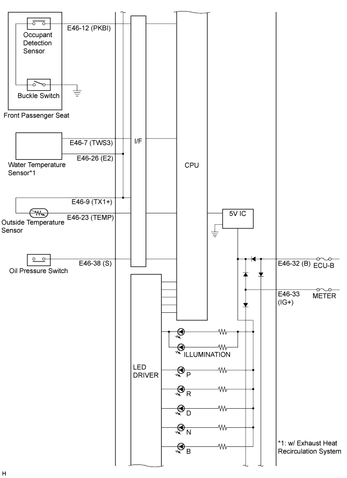
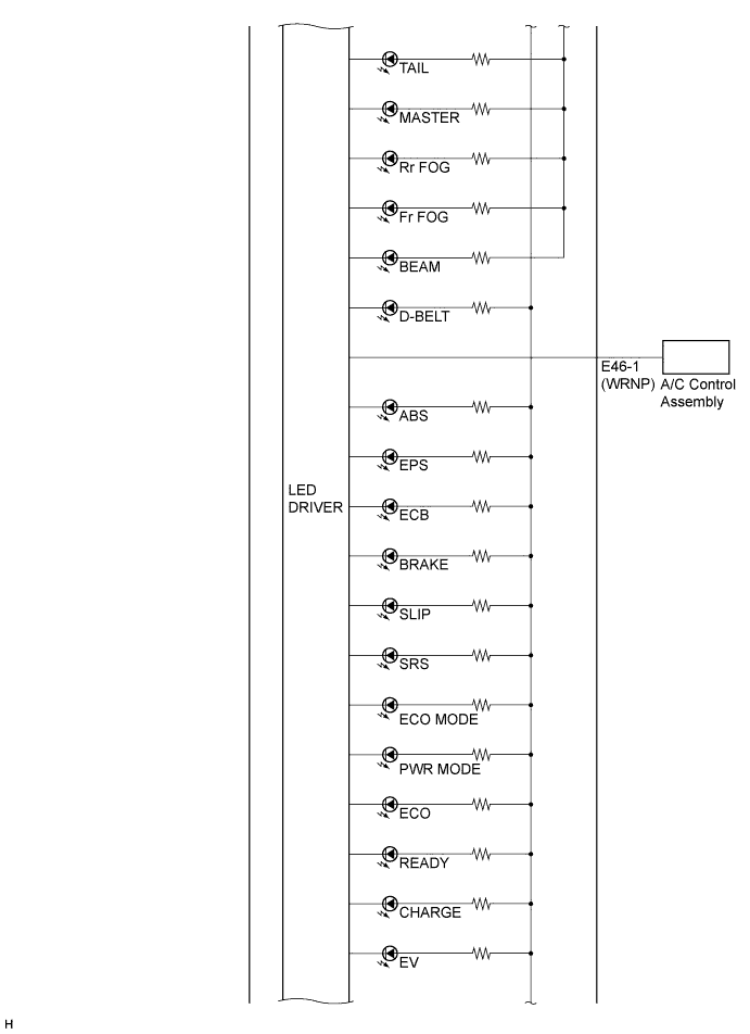
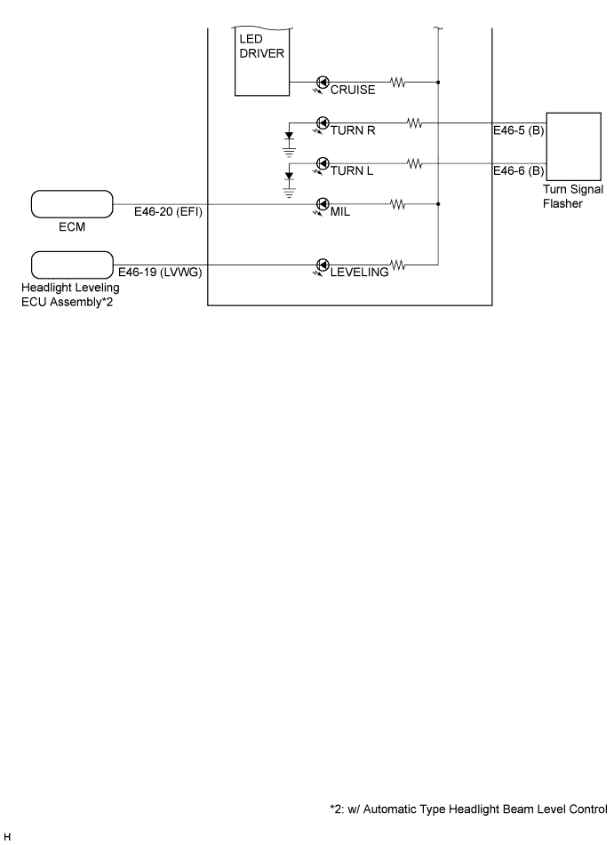
Terminal No. (Symbol) Wire harness side E46 1 (WRNP) A/C Control Assembly 2 - 3 - 4 - 5 (B) Turn Signal Flasher 6 (B) Turn Signal Flasher 7 (TWS3) Water Temperature Sensor*1 8 - 9 (TX1+) Ambient Temperature Sensor 10 (E) Fuel Sender Gauge Assembly 11 - 12 (PKBI) Front Passenger Seat 13 - 14 - 15 - 16 - 17 - 18 - 19 (LVWG) Headlight Leveling ECU Assembly*2 20 (EFI) ECM 21 (SW1) Steering Pad Switch RH or Steering Pad Switch Assembly 22 - 23 (TEMP) Ambient Temperature Sensor 24 - 25 (L) Fuel Sender Gauge Assembly 26 (E2) Water Temperature Sensor*1 27 (CANH) CAN Communication Line 28 (CANL) CAN Communication Line 29 - 30 (ET) Ground 31 - 32 (B) ECU-B Fuse 33 (IG+) METER Fuse 34 - 35 (SI) Skid Control ECU 36 (+S) Each part that uses speed signal 37 - 38 (S) Oil Pressure Switch Assembly 39 - 40 -
-
*1: w/ Exhaust Heat Recirculation System
-
*2: w/ Automatic Type Headlight Beam Level Control
-