AIRBAG SYSTEM DIAGNOSIS SYSTEM
-
CHECK DLC3
-
Check the DLC3 Click here.
-
-
FUNCTION OF SRS WARNING LIGHT
-
Primary check
-
Turn the power switch off. Wait for at least 2 seconds, then turn the power switch on (IG). The SRS warning light comes on for approximately 6 seconds and the diagnosis of the airbag system (including the seat belt pretensioners) is performed.
Tech Tips
If malfunctions are detected during the primary check, the SRS warning light remains on even after the primary check period of approximately 6 seconds.
-
-
Constant check
-
After the primary check, the center airbag sensor assembly constantly monitors the airbag system for malfunctions.
Tech Tips
If malfunctions are detected during the constant check, the center airbag sensor assembly functions as follows:
-
The SRS warning light comes on.
-
The SRS warning light goes off, and then comes on. This indicates a source voltage drop. The SRS warning light goes off 10 seconds after the source voltage returns to normal.
-
-
-
Review
-
When the airbag system is normal:
The SRS warning light comes on only during the primary check period of approximately 6 seconds after the power switch is turned on (IG).
-
When the airbag system is malfunctioning:
-
The SRS warning light remains on even after the primary check period.
-
The SRS warning light goes off after the primary check, but comes on again during the constant check.
-
The SRS warning light does not come on when turning the power switch from off to on (IG).
Tech Tips
The center airbag sensor assembly keeps the SRS warning light on if the airbag has been deployed.
-
-
-
-
SRS WARNING LIGHT CHECK
-
Turn the power switch on (IG), and check that the SRS warning light comes on for approximately 6 seconds (primary check).
-
Check that the SRS warning light goes off approximately 6 seconds after the power switch is turned on (IG) (constant check).
Tech Tips
When any of the following symptoms occur, refer to Problem Symptoms Table Click here.
-
The SRS warning light comes on occasionally after the primary check period.
-
The SRS warning light comes on, but a DTC is not output.
-
The power switch is turned from off to on (IG), but the SRS warning light does not come on.
-
-
-
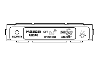
FUNCTION OF PASSENGER AIRBAG ON/OFF INDICATOR (WITH AIRBAG CUT OFF SWITCH)
-
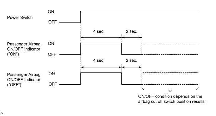
Turn the power switch on (IG).
-
The passenger airbag ON/OFF indicator ("ON" and "OFF") comes on for approximately 4 seconds, then goes off for approximately 2 seconds.
-
Approximately 6 seconds after the power switch is turned on (IG), the passenger airbag ON/OFF indicator will be ON/OFF depending on the conditions listed below.
Airbag Cut OFF Switch Passenger Airbag ON/OFF Indicator SRS Warning Light ON Indicator OFF Indicator ON ON OFF OFF OFF OFF ON OFF Switch failure OFF ON ON Tech Tips
If the passenger airbag ON/OFF indicator does not operate as specified in the table according to the airbag cut off switch status, and the SRS warning light is off, no DTC will be output. Therefore, perform troubleshooting for Trouble in Passenger Airbag ON/OFF Indicator Click here.
-
-
PASSENGER AIRBAG ON/OFF INDICATOR CHECK (WITH AIRBAG CUT OFF SWITCH)
-
Turn the power switch on (IG).
-
Check that the passenger airbag ON/OFF indicator ("ON" and "OFF") comes on for approximately 4 seconds, then goes off for approximately 2 seconds.
Tech Tips
Refer to the table in step 4 regarding the passenger airbag ON/OFF indicator when the power switch is turned on (IG) and approximately 6 seconds elapse.
-
-
ACTIVATION PREVENTION MECHANISM
-
Function of activation prevention mechanism
-
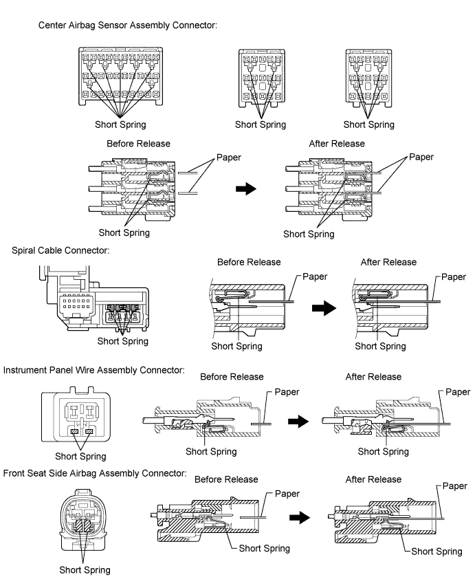
An activation prevention mechanism is built into the connector (on the center airbag sensor assembly side) of the airbag system squib circuit to prevent accidental airbag activation.
-
This mechanism closes the circuit when the connector is disconnected by bringing the short spring into contact with the terminals and insulating the circuit from external power sources to prevent accidental airbag activation.
-
-
Releasing of activation prevention mechanism
-
To release the activation prevention mechanism, insert a piece of paper with the same thickness as the male terminal (approximately 0.5 mm (0.0197 in.)) between the terminals and short spring to break the connection.
-
Refer to the following illustrations concerning connectors utilizing the activation prevention mechanism and its release method.
CAUTION:
Never release the activation prevention mechanism on the squib connector even when inspecting with the squib disconnected.
Note
-
Do not release the activation prevention mechanism unless specially directed by the troubleshooting procedure.
-
To prevent the terminal and short spring from being damaged, always use a piece of paper with the same thickness as the male terminal.
-
-
-