ENGINE HOOD COURTESY SWITCH INSTALLATION
-
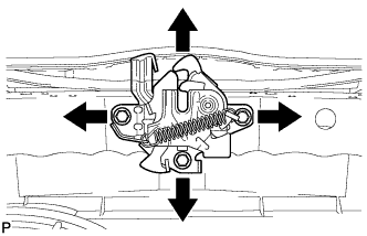
INSTALL HOOD LOCK ASSEMBLY
-
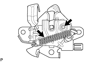
Apply MP grease to the sliding areas of the lock.
-
Install the hood lock assembly with the 3 bolts.
- Torque:
- 7.5 N*m { 77 kgf*cm, 66 in.*lbf }
-
Connect the hood lock control cable.
-
Connect the connector.
-
-
INSPECT HOOD SUB-ASSEMBLY
-
Check that the clearance measurements of areas A through F are within each standard range.
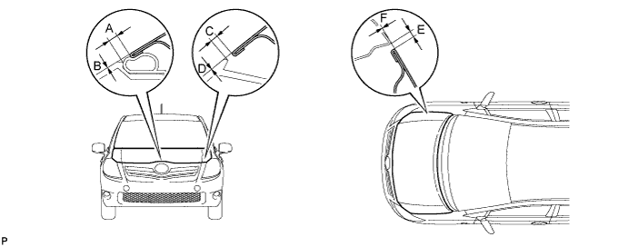
Standard Clearance Area Measurement Area Measurement A 3.1 to 6.1 mm (0.122 to 0.240 in.) D -1.4 to 1.6 mm (-0.0551 to 0.0630 in.) B -1.5 to 1.5 mm (-0.0591 to 0.0591 in.) E 2.3 to 5.3 mm (0.0906 to 0.209 in.) C 1.7 to 4.7 mm (0.0669 to 0.185 in.) F -1.0 to 1.0 mm (-0.0394 to 0.0394 in.)
-
-
ADJUST HOOD SUB-ASSEMBLY
-
Horizontally and vertically adjust the hood.
-
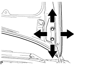
Loosen the 4 hinge bolts of the hood.
-
Adjust the clearance between the hood and front fender by moving the hood.
-
Tighten the 4 hinge bolts after the adjustment.
- Torque:
- 13 N*m { 133 kgf*cm, 10 ft.*lbf }
-
-
Adjust the height of the front end of the hood using the cushion rubber.
-
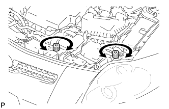
Adjust the 2 cushion rubbers so that the heights of the hood and fender are aligned.
Tech Tips
Raise or lower the front end of the hood by turning the cushion rubber.
-
-
Adjust the hood lock.
-
Loosen the 3 bolts.
-
Tighten the bolts after the adjustment.
- Torque:
- 7.5 N*m { 77 kgf*cm, 66 in.*lbf }
-
Check that the striker can engage with the hood lock smoothly.
-
-
-
INSTALL FRONT BUMPER ASSEMBLY
-
Connect the 2 fog light connectors.
-
w/ Headlight Cleaner System:
-
Fill up washer jar with washer fluid Click here.
-
-
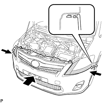
Engage the 6 claws and install the front bumper assembly.
-
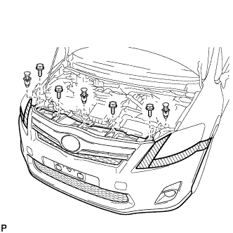
Install the 4 bolts and 3 clips.
-
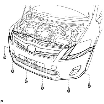
Install the 6 screws.
-
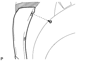
Install the clip.
Tech Tips
Use the same procedure for the RH side and LH side.
-
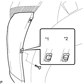
Text in Illustration *1 Correct *2 Incorrect Install the pin hold clip.
Note
Insert the pin hold clip with the slot aligned vertically. Do not rotate the clip after inserting it. After installation, confirm that the slot is vertical.
Tech Tips
Use the same procedure for the RH side and LH side.
-
Remove the protective tape.
-
-
ADJUST FOG LIGHT AIMING