ELECTRICAL KEY OSCILLATOR (for Front Door) REMOVAL
-
REMOVE FRONT DOOR INSIDE HANDLE BEZEL
-
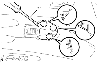
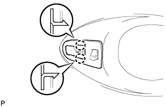
Text in Illustration *1 Protective Tape Using a screwdriver with the tip wrapped with protective tape, disengage the 3 claws, and remove the front door inside handle bezel.
-
-
REMOVE DOOR ASSIST GRIP COVER
-
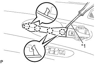
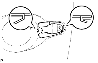
Text in Illustration *1 Protective Tape Using a screwdriver with the tip wrapped with protective tape, disengage the 4 claws and remove the door assist grip cover.
-
-
REMOVE FRONT DOOR TRIM BOARD SUB-ASSEMBLY
-
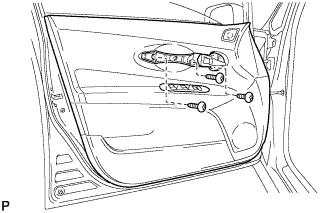
Remove the 3 screws.
-
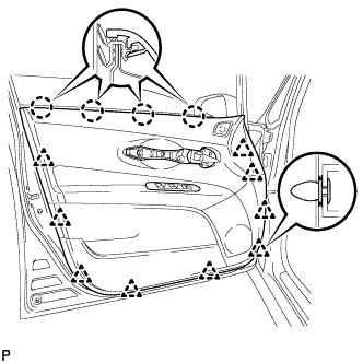
Using a clip remover, disengage the 9 clips.
-
Disengage the 4 claws and separate the front door trim board sub-assembly from the front door inner glass weatherstrip.
-
Disengage the 2 claws and disconnect the front door inside handle sub-assembly.
-
Disconnect each connector.
-
-
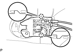
REMOVE FRONT DOOR INSIDE HANDLE SUB-ASSEMBLY
-
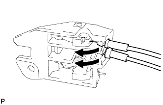
Disconnect the front door lock remote control cable and front door inside locking cable, and remove the front door inside handle sub-assembly.
-
-
REMOVE FRONT DOOR INNER GLASS WEATHERSTRIP
-
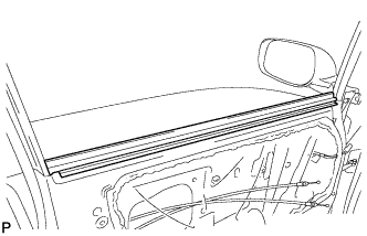
Remove the front door inner glass weatherstrip from the front door panel.
-
-
REMOVE FRONT DOOR SERVICE HOLE COVER
-
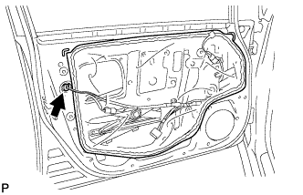
Disconnect the connector.
-
Remove the front door service hole cover.
Tech Tips
Remove the remaining butyl tape on the door.
-
-
REMOVE FRONT DOOR GLASS SUB-ASSEMBLY
-
Connect the negative battery terminal.
-
Connect the power window regulator master switch assembly and move the front door glass sub-assembly so that the door glass bolts can be seen.
-
Disconnect the negative battery terminal and power window regulator master switch assembly.
-
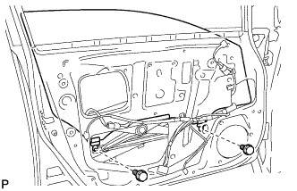
Remove the 2 bolts.
Note
After the bolts are removed, the door glass may fall, causing damage.
-
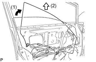
Remove the front door glass sub-assembly as shown in the illustration.
Note
Do not damage the door glass.
-
-
REMOVE FRONT DOOR GLASS RUN
-
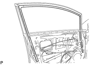
Remove the front door glass run.
-
-
REMOVE FRONT DOOR REAR LOWER FRAME SUB-ASSEMBLY
-
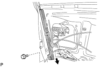
Remove the bolt and front door rear lower frame sub-assembly as shown in the illustration.
-
-
REMOVE FRONT DOOR OUTSIDE HANDLE COVER
-
Remove the hole plug.
-
Using a T30 "TORX" socket wrench, loosen the screw and remove the front door outside handle cover and the door lock key cylinder as a unit.
Tech Tips
The screw cannot be removed because it is integrated into the front door outside handle frame sub-assembly.
-
Using a screwdriver, disengage the 2 claws and remove the front door outside handle cover.
-
-
REMOVE FRONT DOOR OUTSIDE HANDLE ASSEMBLY
-
Disconnect the connector.
-
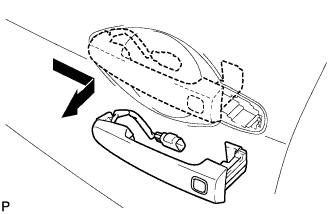
Remove the front door outside handle assembly as shown in the illustration.
-
-
REMOVE FRONT DOOR FRONT OUTSIDE HANDLE PAD
-
Disengage the 2 claws and remove the front door front outside handle pad.
-
-
REMOVE FRONT DOOR REAR OUTSIDE HANDLE PAD
-
Disengage the 2 claws and remove the front door rear outside handle pad.
-
-
REMOVE FRONT DOOR LOCK ASSEMBLY
-
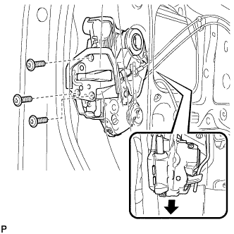
Using a T30 "TORX" socket wrench, remove the 3 screws.
-
Slide the front door lock assembly downward, and remove the front door lock assembly and cables as a unit.
-
Remove the door lock wiring harness seal from the front door lock assembly.
-
-
REMOVE FRONT DOOR OUTSIDE HANDLE FRAME SUB-ASSEMBLY
-
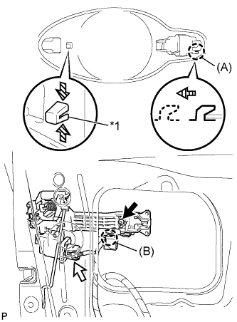
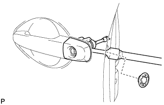
Text in Illustration *1 Grommet Using a T30 "TORX" socket wrench, remove the screw.
-
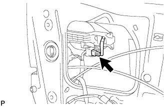
Disconnect the connector.
-
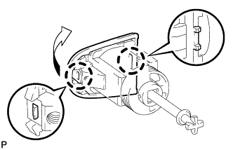
Disengage the claw (B).
-
Using pliers, disengage the grommet as shown in the illustration.
-
Disengage the claw (A) and remove the front door outside handle frame sub-assembly.
-
-
REMOVE DOOR ELECTRICAL KEY OSCILLATOR
-
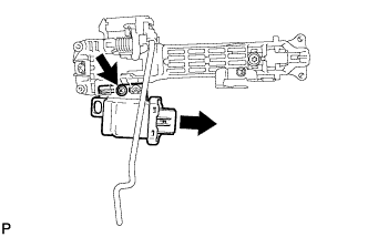
Remove the screw and the door electrical key oscillator.
-