THEFT DETERRENT SYSTEM Glass Breakage Sensor Circuit
DESCRIPTION
When the glass breakage sensor detects that the back door glass is tapped or broken, the sensor will set off an alarm for 27.5 seconds.
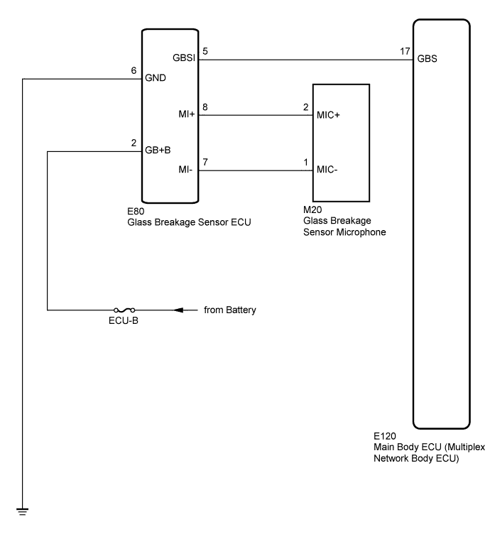
WIRING DIAGRAM
INSPECTION PROCEDURE
Note
Inspect the fuses for circuits related to this system before performing the following inspection procedure.
PROCEDURE
-
READ VALUE USING INTELLIGENT TESTER
-
Connect the intelligent tester to the DLC3.
-
Turn the power switch on (IG).
-
Turn the intelligent tester main switch on.
-
Enter the following menus: Body / Main Body / Data List.
-
According to the display on the intelligent tester, read the Data List.
Main Body (Main Body ECU (Multiplex Network Body ECU)) Tester Display Measurement Item/Range Normal Condition Diagnostic Note Sealed Glas Brak Sen Glass breakage sensor connecting/With or Without With: Glass breakage sensor connected
Without: Glass breakage sensor not connected
- OK When tapping on the glass with your finger, "With" is displayed on the intelligent tester screen.
NG 
CHECK HARNESS AND CONNECTOR (BATTERY - GLASS BREAKAGE SENSOR ECU - GROUND) Click here
OK 
PROCEED TO NEXT SUSPECTED AREA SHOWN IN PROBLEM SYMPTOMS TABLE Click here
-
-
CHECK HARNESS AND CONNECTOR (BATTERY - GLASS BREAKAGE SENSOR ECU - GROUND)
-
Disconnect the E80 glass breakage sensor ECU connector.
-
Measure the resistance and voltage according to the value(s) in the table below.
Standard Resistance Tester Connection Condition Specified Condition E80-6 (GND) - Body ground Always Below 1 Ω Standard Voltage Tester Connection Condition Specified Condition E80-2 (GB+B) - Body ground Power switch off 11 to 14 V
NG 
REPAIR OR REPLACE HARNESS OR CONNECTOR
OK 
-
-
CHECK HARNESS AND CONNECTOR (MAIN BODY ECU - GLASS BREAKAGE SENSOR ECU)
-
Disconnect E120 main body ECU (multiplex network body ECU) connector.
-
Measure the resistance according to the value(s) in the table below.
Standard Resistance Tester Connection Condition Specified Condition E120-17 (GBS) - E80-5 (GBSI) Always Below 1 Ω E120-17 (GBS) - Body ground Always 10 kΩ or higher
NG
REPAIR OR REPLACE HARNESS OR CONNECTOR
OK
-
-
CHECK HARNESS AND CONNECTOR (GLASS BREAKAGE SENSOR ECU - GLASS BREAKAGE SENSOR MICROPHONE)
-
Disconnect the M20 glass breakage sensor microphone connector.
-
Measure the resistance according to the value(s) in the table below.
Standard Resistance Tester Connection Condition Specified Condition E80-8 (MI+) - M20-2 (MIC+) Always Below 1 Ω E80-7 (MI-) - M20-1 (MIC-) Always Below 1 Ω E80-8 (MI+) - Body ground Always 10 kΩ or higher E80-7 (MI-) - Body ground Always 10 kΩ or higher
NG
REPAIR OR REPLACE HARNESS OR CONNECTOR
OK
-
-
INSPECT GLASS BREAKAGE SENSOR ECU ASSEMBLY (MICROPHONE OUTPUT)
-
Reconnect the glass breakage sensor ECU, glass breakage sensor microphone and main body ECU (multiplex network body ECU) connectors.
-
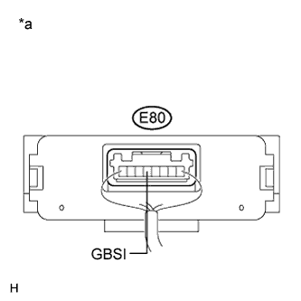
Connect an oscilloscope to terminal E80-5 (GBSI) of the glass breakage sensor ECU and body ground.
-
Turn the power switch on (IG).
Text in Illustration *a Component with harness connected
(Glass Breakage Sensor ECU)
-
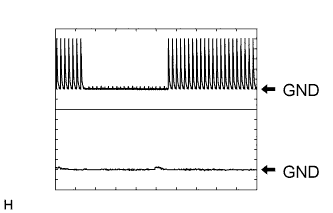
Check the signal waveform according to the condition(s) in the table below.
Item Condition Tester Connection E80-5 (GBSI) - E80-6 (GND) Tool setting 1 V/DIV, 50 ms/DIV Vehicle condition Tap the glass breakage sensor microphone with a hard object such as your fingernail. OK As shown in the illustration
NG
REPLACE GLASS BREAKAGE SENSOR MICROPHONE Click here
OK
REPLACE GLASS BREAKAGE SENSOR ECU ASSEMBLY Click here
-