THEFT DETERRENT SYSTEM TERMINALS OF ECU
-
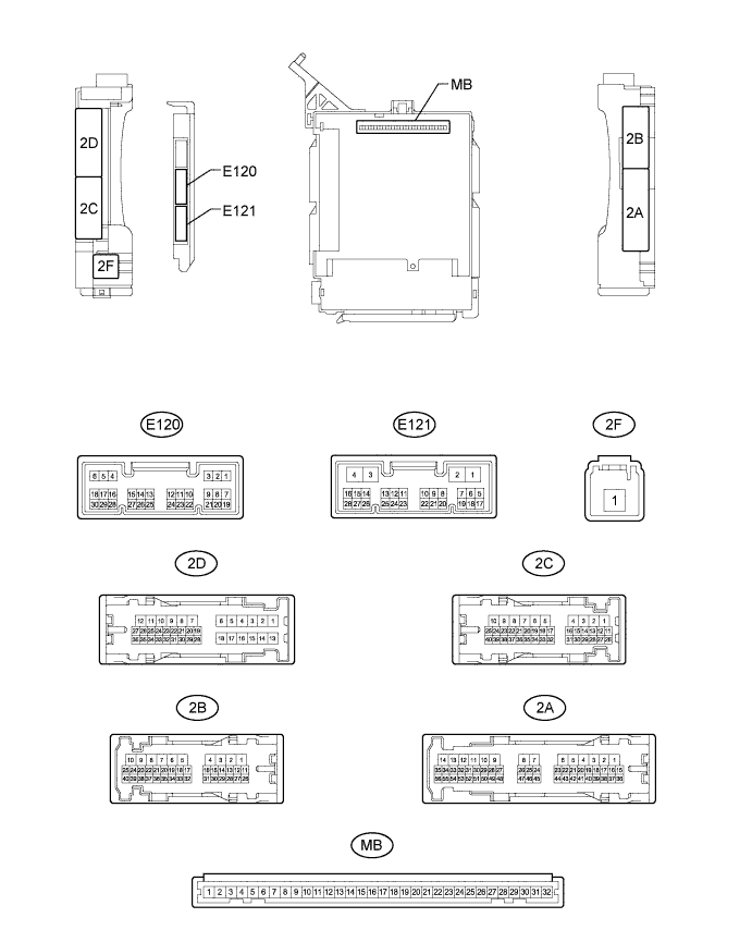
CHECK INSTRUMENT PANEL JUNCTION BLOCK ASSEMBLY AND MAIN BODY ECU (MULTIPLEX NETWORK BODY ECU)
-
Disconnect the main body ECU (multiplex network body ECU) connectors.
-
Measure the resistance and voltage according to the value(s) in the table below.
Tester Connection Wiring Color Terminal Description Condition Specified Condition MB-29 (ACC) - Body ground - ACC power supply Power switch on (ACC) → off 11 to 14 V → Below 1 V MB-32 (IG) - Body ground - IG power supply Power switch on (IG) → off 11 to 14 V → Below 1 V MB-31 (ALTB) - Body ground - Battery power supply Power switch off 11 to 14 V MB-11 (GND1) - Body ground - Ground Always Below 1 Ω E121-3 (GND2) - Body ground W-B - Body ground Ground Always Below 1 Ω MB-2 (FLCY) - Body ground - Front left door courtesy light switch input Front left door closed (OFF) → open (ON) 10 kΩ or higher → Below 1 Ω MB-4 (FRCY) - Body ground - Front right door courtesy light switch input Front right door closed (OFF) → open (ON) 10 kΩ or higher → Below 1 Ω E120-6 (RCTY) - Body ground LG - Body ground Rear courtesy light switch RH input Rear door RH closed (OFF) → open (ON) 10 kΩ or higher → Below 1 Ω E120-23 (LCTY) - Body ground SB - Body ground Rear courtesy light switch LH input Rear door LH closed (OFF) → open (ON) 10 kΩ or higher → Below 1 Ω E120-19 (BCTY) - Body ground LG - Body ground Back door courtesy light switch input Back door closed (OFF) → open (ON) 10 kΩ or higher → Below 1 Ω MB-20 (HCTY) - Body ground - Engine hood courtesy switch input Engine hood open (ON) → closed (OFF) Below 1 Ω → 10 kΩ or higher If the result is not as specified, there may be a malfunction in the wire harness.
-
Reconnect the main body ECU (multiplex network body ECU) connectors.
-
Measure the voltage according to the value(s) in the table below.
Tester Connection Wiring Color Terminal Description Condition Specified Condition E120-18 (LSFR) - Body ground LG - Body ground Driver door lock position switch input Driver door unlock → lock 11 to 14 V E120-7 (LSFL) - Body ground Y - Body ground Front passenger door lock position switch input Front passenger door unlock → lock 11 to 14 V 2D-25 (LSR) - Body ground Y - Body ground Rear left door lock position switch input Rear left door unlock → lock 11 to 14 V 2B-29 (LSR) - Body ground Y - Body ground Rear right door lock position switch input Rear right door unlock → lock 11 to 14 V E121-8 (SSW1) - Body ground G - Body ground Intrusion sensor cancel switch signal Intrusion sensor cancel switch on Below 1 V E121-8 (SSW1) - Body ground G - Body ground Intrusion sensor cancel switch signal Intrusion sensor cancel switch off Pulse generation E121-12 (ISIF) - Body ground V - Body ground Intrusion sensor (theft warning radar sensor) signal input No moving object detected by sensor 11 to 14 V E121-12 (ISIF) - Body ground V - Body ground Intrusion sensor (theft warning radar sensor) signal input Moving object detected by sensor during arming preparation state or armed state Pulse generation E120-3 (HAZ) - Body ground Y - Body ground Turn signal flasher relay signal System in alarm sounding state Below 1 V E121-18 (SSCL) - Body ground L - Body ground Theft warning siren drive Theft warning siren sounding
(Theft deterrent system is in alarm sounding state)
Pulse generation
(Below 1 V ← → 12 V)
E120-17 (GBS) - Body ground V - Body ground Glass breakage sensor drive Always Below 1 V 2A-51 (IND) - Body ground Y - Body ground Security indicator light up Security indicator light on (It lights up only for 27.5 sec. in alarm sounding state.) 3 to 6 V If the result is not as specified, the main body ECU (multiplex network body ECU) or instrument panel junction block assembly may have a malfunction.
-