ENTRY AND START SYSTEM (for Entry Function) All Door Entry Lock/Unlock Functions do not Operate, but Wireless Functions Operate
DESCRIPTION
When the wireless functions can be used to lock and unlock the doors, the communication between the door control receiver and certification ECU (smart key ECU assembly) is normal. When the entry functions do not operate, one of the following may be the cause: 1) entry cancel function is set through customization; 2) malfunction in the entry and start system communication (electrical key transmitter and vehicle); or 3) electrical interference.
INSPECTION PROCEDURE
Note
The entry and start system (for entry function) uses a multiplex communication system (LIN communication system) and CAN communication system. Inspect the communication function by following How to Proceed with Troubleshooting Click here. Troubleshoot the entry and start system (for entry function) after confirming that the communication system is functioning properly.
PROCEDURE
-
READ VALUE USING INTELLIGENT TESTER (ENTRY CANCEL FUNCTION)
-
Connect the intelligent tester to the DLC3.
-
Turn the power switch on (IG).
-
Turn the intelligent tester on.
-
Enter the following menus: Body / Entry & Start / Data List.
-
Read the Data List according to the display on the intelligent tester.
Entry & Start (Certification ECU (Smart Key ECU Assembly)) Tester Display Measurement Item/Range Normal Condition Diagnostic Note Auto Entry Cancel SW Entry function cancel / ON or OFF Mode status displayed - Result Result Proceed to Entry function cancel OFF A Entry function cancel ON B
B 
PERFORM CANCELLATION OF ENTRY KEY CANCEL FUNCTION Click here
A 
-
-
CHECK WAVE ENVIRONMENT
-
Move the electrical key transmitter as described below and perform the operation inspection.
Tech Tips
-
When the electrical key transmitter is brought near the door outside handle assembly or electrical key antenna, the possibility of wave interference decreases, and it can be determined if wave interference is causing the problem symptom.
-
The transmitting waves of the wireless functions and entry functions are the same, but the wave logic is different. Therefore, it is possible that only the wireless functions or only the entry functions are affected by wave interference.
-
-
Bring the electrical key transmitter near the driver door outside handle assembly, and perform a front driver door entry lock and unlock operation check.
Note
If the key is brought within 0.2 m (0.656 ft.) of the door outside handle assembly, communication is not possible.
-
Bring the electrical key transmitter near the front passenger door outside handle assembly, and perform a front passenger door entry lock and unlock operation check.
Note
If the key is brought within 0.2 m (0.656 ft.) of the door outside handle assembly, communication is not possible.
-
Bring the electrical key transmitter near the outside electrical key oscillator (for rear side), and perform an entry back door open function check.
Note
If the key is brought within 0.2 m (0.656 ft.) of the rear bumper, communication is not possible.
Tech Tips
If the inspection result indicates that the problem only occurs in certain locations or times of day, the possibility of wave interference is high. Also, added vehicle components may cause wave interference. If installed, remove them and perform the operation check.
Result Result Proceed to All operation checks fail A Some operation checks are normal B
B
AFFECTED BY WAVE INTERFERENCE
A
-
-
PERFORM KEY DIAGNOSTIC MODE INSPECTION
-
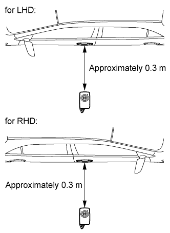
Diagnostic mode inspection (door electrical key oscillator (for driver side))
-
Connect the intelligent tester to the DLC3.
-
Turn the power switch on (IG).
-
Turn the intelligent tester on.
-
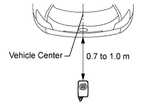
Enter the following menus: Body / Entry & Start / Key Communication Check / Overhead + Driver Side.
-
When the electrical key transmitter is in the position shown in the illustration, check that the wireless door lock buzzer sounds.
-
-
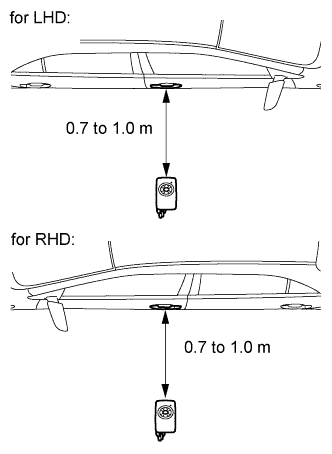
Diagnostic mode inspection (door electrical key oscillator (for front passenger side))
-
Connect the intelligent tester to the DLC3.
-
Turn the power switch on (IG).
-
Turn the intelligent tester on.
-
Enter the following menus: Body / Entry & Start / Key Communication Check / Overhead + Passenger Side.
-
When the electrical key transmitter is in the position shown in the illustration, check that the wireless door lock buzzer sounds.
-
-
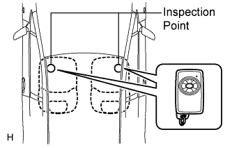
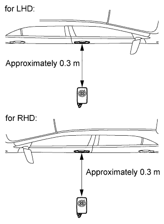
Diagnostic mode inspection (indoor electrical key oscillator (for front floor))
-
Connect the intelligent tester to the DLC3.
-
Turn the power switch on (IG).
-
Turn the intelligent tester on.
-
Enter the following menus: Body / Entry & Start / Key Communication Check / Overhead + Front Room.
-
When the electrical key transmitter is in the position shown in the illustration, check that the wireless door lock buzzer sounds.
-
-
Diagnostic mode inspection (indoor electrical key oscillator (for center floor))
-
Connect the intelligent tester to the DLC3.
-
Turn the power switch on (IG).
-
Turn the intelligent tester on.
-
Enter the following menus: Body / Entry & Start / Key Communication Check / Overhead + Rear Room.
-
When the electrical key transmitter is in the position shown in the illustration, check that the wireless door lock buzzer sounds.
-
-
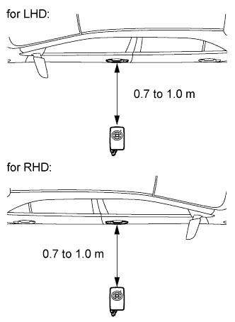
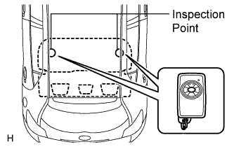
Diagnostic mode inspection (indoor electrical key oscillator (for rear floor))
-
Connect the intelligent tester to the DLC3.
-
Turn the power switch on (IG).
-
Turn the intelligent tester on.
-
Enter the following menus: Body / Entry & Start / Key Communication Check / Overhead + Back Door (inside).
-
When the electrical key transmitter is in the position shown in the illustration, check that the wireless door lock buzzer sounds.
-
-
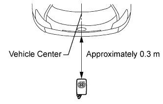
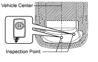
Diagnostic mode inspection (outside electrical key oscillator (for rear side))
-
Connect the intelligent tester to the DLC3.
-
Turn the power switch on (IG).
-
Turn the intelligent tester on.
-
Enter the following menus: Body / Entry & Start / Key Communication Check / Overhead + Back Door.
-
When the electrical key transmitter is in the position shown in the illustration, check that the wireless door lock buzzer sounds.
Result Result Proceed to All diagnostic mode inspections fail A Some diagnostic mode inspections fail (door) B Some diagnostic mode inspections fail (cabin) C Some diagnostic mode inspections fail (outside) D All diagnostic mode inspections are normal E
-
B
GO TO OTHER PROBLEM (Proceed to Problem Symptoms Table for Each Door) Click here
C
GO TO OTHER PROBLEM (Proceed to Room Oscillator does not Recognize Key) Click here
D
GO TO OTHER PROBLEM (Proceed to Problem Symptoms Table) Click here
E
REPLACE CERTIFICATION ECU (SMART KEY ECU ASSEMBLY)
A
-
-
REPLACE ELECTRICAL KEY TRANSMITTER
-
Replace the electrical key transmitter.
NEXT
-
-
REGISTER ELECTRICAL KEY TRANSMITTER
-
Register the electrical key transmitter.
NEXT
-
-
CHECK ELECTRICAL KEY TRANSMITTER (OPERATION)
-
Check that the entry functions operate normally Click here.
OK Entry functions operate normally.
NG
REPLACE CERTIFICATION ECU (SMART KEY ECU ASSEMBLY)
OK 
END (ELECTRICAL KEY TRANSMITTER WAS DEFECTIVE)
-