ENGINE IMMOBILISER SYSTEM Security Indicator Light Does not Blink
DESCRIPTION
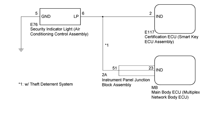
The security indicator light comes on due to a signal received from the certification ECU (smart key ECU assembly) while the engine immobiliser is set, or the main body ECU (multiplex network body ECU) while the theft deterrent system is in the armed state or alarm sounding state*1.
-
*1: w/ Theft Deterrent System
WIRING DIAGRAM
INSPECTION PROCEDURE
Note
If the certification ECU (smart key ECU assembly) is replaced, register all the keys.
PROCEDURE
-
SYSTEM CHECK
-
Check the vehicle specification.
Result Result Proceed to w/o Theft Deterrent System A w/ Theft Deterrent System B
B 
PERFORM ACTIVE TEST USING INTELLIGENT TESTER Click here
A 
-
-
PERFORM ACTIVE TEST USING INTELLIGENT TESTER
-
Connect the intelligent tester to the DLC3.
-
Turn the power switch on (IG).
-
Turn the intelligent tester on.
-
Enter the following menus: Body / Entry&Start / Active Test.
-
Perform the Active Test according to the display on the intelligent tester.
Entry&Start (Certification ECU (Smart Key ECU Assembly)) Tester Display Test Part Control Range Diagnostic Note Security Indicator Security indicator light ON or OFF - OK The security indicator light turns on and off according to operation via the intelligent tester.
NG
INSPECT SECURITY INDICATOR LIGHT (AIR CONDITIONING CONTROL ASSEMBLY) Click here
OK 
REPLACE CERTIFICATION ECU (SMART KEY ECU ASSEMBLY)
-
-
INSPECT SECURITY INDICATOR LIGHT (AIR CONDITIONING CONTROL ASSEMBLY)
-
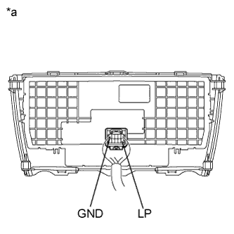
Text in Illustration *a Component without harness connected
(Security Indicator Light (Air Conditioning Control Assembly))
Remove the security indicator light (air conditioning control assembly) Click here.
-
Apply battery voltage between the terminals of the indicator, and check the lighting condition of the security indicator light.
Standard Measurement Condition Specified Condition Battery positive (+) → Terminal 6 (LP)
Battery negative (-) → Terminal 5 (GND)
Security indicator light comes on Note
-
If the positive (+) lead and the negative (-) lead are incorrectly connected, the security indicator light will not come on.
-
Voltage of more than 12 V will damage the security indicator light.
-
If the voltage is too low, the security indicator light will not come on.
-
NG 
REPLACE SECURITY INDICATOR LIGHT (AIR CONDITIONING CONTROL ASSEMBLY) Click here
OK
-
-
CHECK HARNESS AND CONNECTOR (SECURITY INDICATOR LIGHT - BODY GROUND AND CERTIFICATION ECU)
-
Disconnect the certification ECU (smart key ECU assembly) connector.
-
Measure the resistance according to the value(s) in the table below.
Standard Resistance Tester Connection Condition Specified Condition E76-6 (LP) - Body ground Always 10 kΩ or higher E76-6 (LP) - E117-2 (IND) Always Below 1 Ω E76-5 (GND) - Body ground Always Below 1 Ω
NG
REPAIR OR REPLACE HARNESS OR CONNECTOR
OK
REPLACE CERTIFICATION ECU (SMART KEY ECU ASSEMBLY)
-
-
PERFORM ACTIVE TEST USING INTELLIGENT TESTER
-
Connect the intelligent tester to the DLC3.
-
Turn the power switch on (IG).
-
Turn the intelligent tester on.
-
Enter the following menus: Body / Entry&Start or Main Body / Active Test.
-
Perform the Active Test according to the display on the intelligent tester.
Entry&Start (Certification ECU (Smart Key ECU Assembly)) Tester Display Test Part Control Range Diagnostic Note Security Indicator Security indicator light ON or OFF - Main Body (Main Body ECU (Multiplex Network Body ECU)) Tester Display Test Part Control Range Diagnostic Note Security Indicator Security indicator light ON or OFF - Result Result Proceed to Security indicator light operation is not normal by performing the Active Test of "Main Body" and "Entry&Start" A
-
Security indicator light operation is not normal by performing the Active Test of "Entry&Start"
-
Security indicator light operation is normal by performing the Active Test "Main Body"
B
-
Security indicator light operation is normal by performing the Active Test of "Entry&Start"
-
Security indicator light operation is not normal by performing the Active Test "Main Body"
C -
B
CHECK HARNESS AND CONNECTOR (CERTIFICATION ECU - SECURITY INDICATOR LIGHT) Click here
C
CHECK HARNESS AND CONNECTOR (MAIN BODY ECU - SECURITY INDICATOR LIGHT) Click here
A
-
-
INSPECT SECURITY INDICATOR LIGHT (AIR CONDITIONING CONTROL ASSEMBLY)
-
Text in Illustration *a Component without harness connected
(Security Indicator Light (Air Conditioning Control Assembly))
Remove the security indicator light (air conditioning control assembly) Click here.
-
Apply battery voltage between the terminals of the indicator, and check the lighting condition of the security indicator light.
Standard Measurement Condition Specified Condition Battery positive (+) → Terminal 6 (LP)
Battery negative (-) → Terminal 5 (GND)
Security indicator light comes on Note
-
If the positive (+) lead and the negative (-) lead are incorrectly connected, the security indicator light will not come on.
-
Voltage of more than 12 V will damage the security indicator light.
-
If the voltage is too low, the security indicator light will not come on.
-
NG
REPLACE SECURITY INDICATOR LIGHT (AIR CONDITIONING CONTROL ASSEMBLY) Click here
OK
-
-
CHECK HARNESS AND CONNECTOR (SECURITY INDICATOR LIGHT - MAIN BODY ECU, CERTIFICATION ECU AND BODY GROUND)
-
Disconnect the certification ECU (smart key ECU assembly) connector.
-
Disconnect the main body ECU (multiplex network body ECU) connector.
-
Measure the resistance according to the value(s) in the table below.
Standard Resistance Tester Connection Condition Specified Condition E76-6 (LP) - Body ground Always 10 kΩ or higher E76-6 (LP) - E117-2 (IND) Always Below 1 Ω E76-6 (LP) - MB-23 (IND) Always Below 1 Ω E76-5 (GND) - Body ground Always Below 1 Ω
NG
REPAIR OR REPLACE HARNESS OR CONNECTOR
OK
-
-
CHECK SECURITY INDICATOR LIGHT OPERATION
-
Install the security indicator light (air conditioning control assembly) Click here.
-
Reconnect the certification ECU (smart key ECU assembly) connector.
-
Check that security indicator light comes on when the engine immobiliser system is set.
OK The security indicator light comes on.
NG
REPLACE CERTIFICATION ECU (SMART KEY ECU ASSEMBLY)
OK
REPLACE MAIN BODY ECU (MULTIPLEX NETWORK BODY ECU)
-
-
CHECK HARNESS AND CONNECTOR (CERTIFICATION ECU - SECURITY INDICATOR LIGHT)
-
Disconnect the certification ECU (smart key ECU assembly) connector.
-
Disconnect the security indicator light (air conditioning control assembly) connector.
-
Measure the resistance according to the value(s) in the table below.
Standard Resistance Tester Connection Condition Specified Condition E76-6 (LP) - Body ground Always 10 kΩ or higher E76-6 (LP) - E117-2 (IND) Always Below 1 Ω
NG
REPAIR OR REPLACE HARNESS OR CONNECTOR
OK
REPLACE CERTIFICATION ECU (SMART KEY ECU ASSEMBLY)
-
-
CHECK HARNESS AND CONNECTOR (MAIN BODY ECU - SECURITY INDICATOR LIGHT)
-
Disconnect the main body ECU (multiplex network body ECU) connector.
-
Disconnect the security indicator light (air conditioning control assembly) connector.
-
Measure the resistance according to the value(s) in the table below.
Standard Resistance Tester Connection Condition Specified Condition E76-6 (LP) - Body ground Always 10 kΩ or higher E76-6 (LP) - MB-23 (IND) Always Below 1 Ω
NG
INSPECT INSTRUMENT PANEL JUNCTION BLOCK ASSEMBLY Click here
OK
REPLACE MAIN BODY ECU (MULTIPLEX NETWORK BODY ECU)
-
-
INSPECT INSTRUMENT PANEL JUNCTION BLOCK ASSEMBLY
-
Remove the instrument panel junction block assembly.
-
Remove the main body ECU (multiplex network body ECU).
-
Measure the resistance according to the value(s) in the table below.
Tech Tips
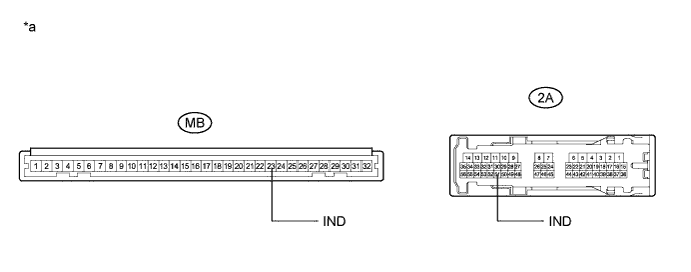
This inspection is to check the line in the instrument panel junction block assembly that connects the wire harness to the built-in main body ECU (multiplex network body ECU).
Standard Resistance Tester Connection Condition Specified Condition 2A-51 (IND) - MB-23 (IND) Always Below 1 Ω 2A-51 (IND) - Body ground Always 10 kΩ or higher Text in Illustration *a Component without harness connected
(Instrument Panel Junction Block Assembly)
- -
NG
REPLACE INSTRUMENT PANEL JUNCTION BLOCK ASSEMBLY
OK
REPAIR OR REPLACE HARNESS OR CONNECTOR
-