TURN SIGNAL FLASHER ASSEMBLY REMOVAL

-
REMOVE UPPER INSTRUMENT PANEL ASSEMBLY
Tech Tips
Refer to the procedure up to Remove Upper Instrument Panel Assembly Click here.
-
REMOVE HEADUP DISPLAY (w/ Headup Display)
-
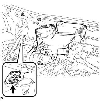
Disconnect the connector.
-
Disengage the clamp.
-
Remove the bolt, 2 nuts and headup display.
-
-
REMOVE NO. 3 SIDE DEFROSTER NOZZLE DUCT
-
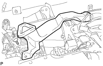
Remove the clip and No. 3 side defroster nozzle duct.
-
-
REMOVE TURN SIGNAL FLASHER ASSEMBLY (for LHD)
-
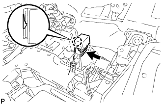
Using a screwdriver, disengage the claw.
-
Disconnect the connector and remove the turn signal flasher assembly.
-
-
REMOVE TURN SIGNAL FLASHER ASSEMBLY (for RHD)
-
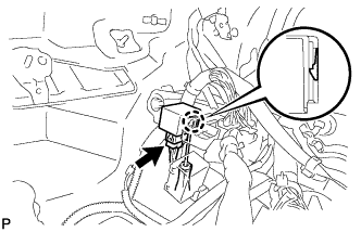
Using a screwdriver, disengage the claw.
-
Disconnect the connector and remove the turn signal flasher assembly.
-